Lexus NX: ACC Signal Circuit
DESCRIPTION
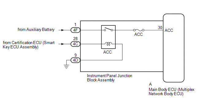
This circuit detects whether the power switch is on (ACC) or off, and sends this information to the main body ECU (multiplex network body ECU).
WIRING DIAGRAM
CAUTION / NOTICE / HINT
NOTICE:
- Inspect the fuses for circuits related to this system before performing the following procedure.
- Recognition code registration is necessary when replacing the main body ECU (multiplex network body ECU).
- If the main body ECU (multiplex network body ECU) is replaced, refer to Registration.
PROCEDURE
| 1. | READ VALUE USING TECHSTREAM (ACC SW) |
(a) Using the Techstream, read the Data List.
Click here .gif)
| Tester Display | Measurement Item | Range | Normal Condition | Diagnostic Note |
|---|---|---|---|---|
| ACC SW | Power switch on (ACC) signal | ON or OFF | ON: Power switch on (ACC) OFF: Power switch off | "ON" is also displayed for this item when the power switch is on (IG). |
| Tester Display |
|---|
| ACC SW |
OK:
The display is as specified in the normal condition column.
| OK | .gif) | PROCEED TO NEXT SUSPECTED AREA SHOWN IN PROBLEM SYMPTOMS TABLE |
|
.gif)
| 2. | CHECK HARNESS AND CONNECTOR (INSTRUMENT PANEL JUNCTION BLOCK ASSEMBLY - BATTERY AND BODY GROUND) |
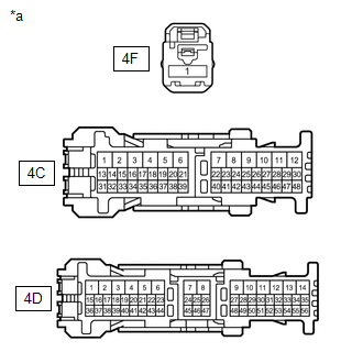
| (a) Disconnect the instrument panel junction block assembly connectors. |
|
(b) Measure the voltage according to the value(s) in the table below.
Standard Voltage:
| Tester Connection | Switch Condition | Specified Condition |
|---|---|---|
| 4F-1 - Body ground | Power switch off | 11 to 14 V |
| 4C-28 - Body ground | Power switch on (ACC) | 11 to 14 V |
(c) Measure the resistance according to the value(s) in the table below.
Standard Resistance:
| Tester Connection | Condition | Specified Condition |
|---|---|---|
| 4D-9 - Body ground | Always | Below 1 Ω |
| NG | | REPAIR OR REPLACE HARNESS OR CONNECTOR |
|
| 3. | CHECK INSTRUMENT PANEL JUNCTION BLOCK ASSEMBLY (ACC RELAY) |
| (a) Remove the instrument panel junction block assembly connectors. Click here |
|
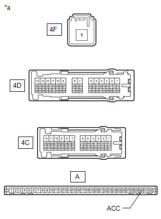
(b) Remove the main body ECU (multiplex network body ECU) from the instrument panel junction block assembly.
Click here
(c) Measure the resistance according to the value(s) in the table below.
Standard Resistance:
| Tester Connection | Switch Condition | Specified Condition |
|---|---|---|
| 4F-1 - A-30 (ACC) | Not connected | 10 kΩ or higher |
| 4F-1 - A-30 (ACC) | Battery positive (+) → 4C-28 Battery negative (-) → 4D-9 | Below 1 Ω |
| OK | | REPLACE MAIN BODY ECU (MULTIPLEX NETWORK BODY ECU) |
| NG | | REPLACE INSTRUMENT PANEL JUNCTION BLOCK ASSEMBLY |
READ NEXT:
 Door Courtesy Switch Circuit
DESCRIPTION The main body ECU (multiplex network body ECU) receives a door open or closed signal from each door courtesy light switch. WIRING DIAGRAM CAUTION / NOTICE / HINT NOTICE:
Recognition co
Back Door Courtesy Switch Circuit
DESCRIPTION The main body ECU (multiplex network body ECU) receives a back door open or closed signal from the back door courtesy light switch. WIRING DIAGRAM CAUTION / NOTICE / HINT NOTICE:
Recog
Interior Light Circuit
DESCRIPTION The main body ECU (multiplex network body ECU) controls the map light assembly and spot light assembly. WIRING DIAGRAM CAUTION / NOTICE / HINT NOTICE:
Recognition code registration is
SEE MORE:
Pointer Displayed/not Displayed Repeatedly
WIRING DIAGRAM CAUTION / NOTICE / HINT NOTICE:
Inspect the fuses for circuits related to this system before performing the following procedure.
When replacing the radio receiver assembly or navigation ECU, always replace it with a new one.
If a radio receiver assembly or navigation ECU which w
Engine Oil Cooler
ComponentsCOMPONENTS ILLUSTRATION *1 OIL COOLER ASSEMBLY *2 GASKET *3 SEAL WASHER *4 UNION BOLT N*m (kgf*cm, ft.*lbf): Specified torque ● Non-reusable part RemovalREMOVAL PROCEDURE 1. REMOVE EXHAUST MANIFOLD CONVERTER SUB-ASSEMBLY Click here 2. DRAIN ENGINE OI
