Lexus NX: Adjustment
ADJUSTMENT
CAUTION / NOTICE / HINT
HINT:
- Use the same procedure for the RH and LH sides.
- The procedure listed below is for the LH side.
-
Centering bolts are used to mount the door hinge to the vehicle body and door. The door cannot be adjusted with the centering bolts on. Substitute the centering bolts for standard bolts when making adjustments.
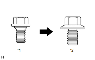
*1
Centering Bolt
*2
Standard Bolt
-
A bolt without a torque specification is shown in the standard bolt chart.
Click here
.gif)
PROCEDURE
1. INSPECT REAR DOOR PANEL SUB-ASSEMBLY LH
(a) Check that the clearance measurements of areas A to H are within the standard ranges.
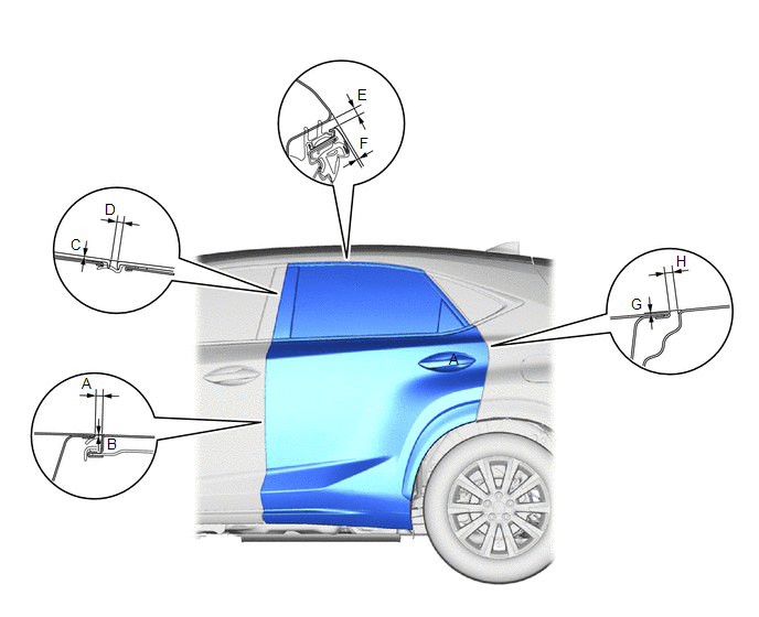
Standard Clearance:
| Area | Measurement | Area | Measurement |
|---|---|---|---|
| A | 2.6 to 5.0 mm (0.1024 to 0.1969 in.) | B | -1.2 to 1.2 mm (-0.0472 to 0.0472 in.) |
| C (Reference) | 0 mm (0 in.) | D (Reference) | 4.1 mm (0.1614 in.) |
| E | 3.05 to 7.05 mm (0.1201 to 0.2776 in.) | F | 1.05 to 5.05 mm (0.0413 to 0.1988 in.) |
| G | -1.5 to 1.5 mm (-0.0591 to 0.0591 in.) | H | 2.0 to 5.0 mm (0.0787 to 0.1969 in.) |
2. ADJUST REAR DOOR PANEL SUB-ASSEMBLY LH
| (a) Using SST, loosen the hinge bolts on the body and adjust the door position. SST: 09812-00010 |
|
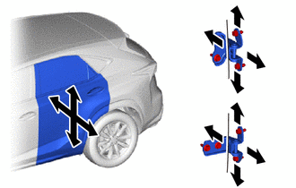
(b) Tighten the hinge bolts on the body after the adjustment.
Torque:
21 N·m {214 kgf·cm, 15 ft·lbf}
| (c) Loosen the hinge bolts on the door and adjust the door position. |
|
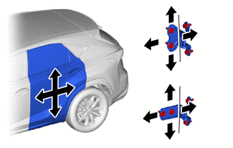
(d) Tighten the hinge bolts on the door after the adjustment.
Torque:
26 N·m {265 kgf·cm, 19 ft·lbf}
| (e) Detach the 4 claws and remove the striker cover. |
|
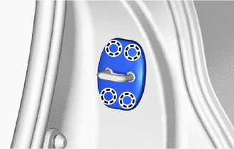
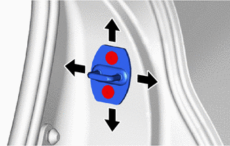
| (f) Using a T40 "TORX" socket wrench, adjust the striker position by slightly loosening the striker mounting screws and hitting the striker with a plastic-faced hammer. Torque: 23 N·m {235 kgf·cm, 17 ft·lbf} |
|
(g) Attach the 4 claws and install the striker cover.
READ NEXT:
 Reassembly
REASSEMBLY CAUTION / NOTICE / HINT HINT:
Use the same procedure for the RH and LH sides.
The procedure listed below is for the LH side.
A bolt without a torque specification is shown in the sta
Rear Door Opening Trim Weatherstrip
ComponentsCOMPONENTS ILLUSTRATION *1 REAR DOOR OPENING TRIM WEATHERSTRIP LH *2 REAR DOOR SCUFF PLATE LH RemovalREMOVAL CAUTION / NOTICE / HINT HINT:
Use the same procedure for the RH
Relay
InspectionINSPECTION PROCEDURE 1. INSTALL RELAY BLOCK ASSEMBLY (a) Preparations for inspection (1) Connect the positive battery terminal to terminal 2 of the fuel lid opener relay and the negative
SEE MORE:
Air Mix Damper Control Servo Motor Circuit (Passenger Side) (B1441)
DESCRIPTION The No. 1 air conditioning radiator damper servo sub-assembly (front passenger side air mix) sends pulse signals to indicate the damper position to the air conditioning amplifier assembly. The air conditioning amplifier assembly activates the motor (normal or reverse) based on these sign
Removal
REMOVAL CAUTION / NOTICE / HINT CAUTION: Wear protective gloves. Sharp areas on the parts may injure your hands. HINT:
Use the same procedure for the RH and LH sides.
The procedure listed below is for the LH side.
PROCEDURE 1. PRECAUTION CAUTION: Be sure to read Precaution thoroughly before
