Lexus NX: Ambient Temperature Sensor
Components
COMPONENTS
ILLUSTRATION
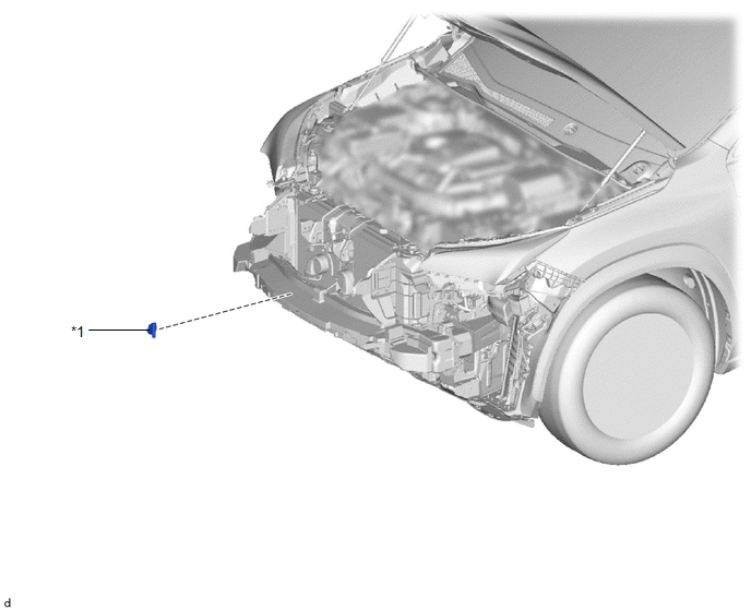
| *1 | THERMISTOR ASSEMBLY (AMBIENT TEMPERATURE SENSOR) | - | - |
Removal
REMOVAL
PROCEDURE
1. REMOVE FRONT BUMPER ASSEMBLY
(a) for Sport Package:
Click here .gif)
(b) except Sport Package:
Click here
2. REMOVE THERMISTOR ASSEMBLY (AMBIENT TEMPERATURE SENSOR)
| (a) Detach the clamp. |
|
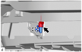
(b) Disconnect the connector and remove the thermistor assembly (ambient temperature sensor).
Inspection
INSPECTION
PROCEDURE
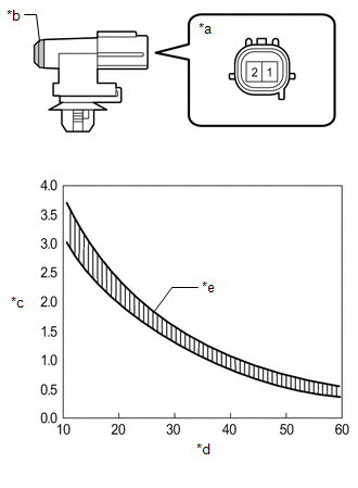
1. INSPECT THERMISTOR ASSEMBLY (AMBIENT TEMPERATURE SENSOR)
| (a) Measure the resistance according to the value(s) in the table below. Standard Resistance:
NOTICE:
HINT: As the temperature increases, the resistance decreases (see the graph).
|
|
Installation
INSTALLATION
PROCEDURE
1. INSTALL THERMISTOR ASSEMBLY (AMBIENT TEMPERATURE SENSOR)
(a) Connect the connector.
(b) Attach the clamp to install the thermistor assembly (ambient temperature sensor).
2. INSTALL FRONT BUMPER ASSEMBLY
(a) for Sport Package:
Click here .gif)
(b) except Sport Package:
Click here
READ NEXT:
 Components
COMPONENTS ILLUSTRATION *1 BLOWER ASSEMBLY - - ILLUSTRATION *1 AIR FILTER CASE *2 AIR REFINER ELEMENT *3 BLOWER WITH FAN MOTOR SUB-ASSEMBLY *4 NO. 1 BLOWER DAMPER SERV
Removal
REMOVAL PROCEDURE 1. REMOVE AIR CONDITIONING UNIT ASSEMBLY Click here 2. REMOVE BLOWER ASSEMBLY (a) Disconnect the No. 1 blower damper servo sub-assembly connector. (b) Detach the 3
SEE MORE:
Terminals Of Ecu
TERMINALS OF ECU HEADUP DISPLAY (METER MIRROR SUB-ASSEMBLY) (a) Measure the voltage and resistance according to the value(s) in the table below. Terminal No. (Symbol) Wiring Color Terminal Description Condition Specified Condition J5-1 (IG) - Body ground B - Body ground Power swi
Data List / Active Test
DATA LIST / ACTIVE TEST DATA LIST NOTICE: In the table below, the values listed under "Normal Condition" are reference values. Do not depend solely on these reference values when deciding whether a part is faulty or not. (a) Connect the Techstream to the DLC3. (b) Turn the power switch on (IG). (c)
