Lexus NX: Back Door Courtesy Switch Circuit
DESCRIPTION
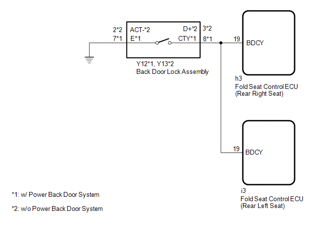
The fold seat control ECU receives the switch operation signal, driving condition signal and back door open/close signal from the back door lock assembly. The fold seat control ECU actives the rear seat according to these signals.
WIRING DIAGRAM
PROCEDURE
| 1. | CHECK BACK DOOR LOCK ASSEMBLY (BACK DOOR COURTESY LIGHT SWITCH) |
(a) Check that the luggage compartment light is on and off according to the back door operation.
OK:
Luggage compartment light is on and off normally according to the back door operation.
| NG | .gif) | GO TO LIGHTING SYSTEM |
|
.gif)
| 2. | CHECK HARNESS AND CONNECTOR (BACK DOOR LOCK ASSEMBLY - FOLD SEAT CONTROL ECU AND BODY GROUND) |
(a) Disconnect the Y12*1 or Y13*2 back door lock assembly connector.
- *1: w/ Power Back Door System
- *2: w/o Power Back Door System
(b) Disconnect the h3*1 or i3*2 fold seat control ECU connector.
- *1: Rear Right Seat
- *2: Rear Left Seat
(c) Measure the resistance according to the value(s) in the table below.
Standard Resistance:
w/ Power Back Door System (Rear Right Seat)
| Tester Connection | Condition | Specified Condition |
|---|---|---|
| Y12-8 (CTY) - h3-19 (BDCY) | Always | Below 1 Ω |
| Y12-7 (E) - Body ground | Always | Below 1 Ω |
| Y12-8 (CTY) or h3-19 (BDCY) - Body ground | Always | 10 kΩ or higher |
w/o Power Back Door System (Rear Right Seat)
| Tester Connection | Condition | Specified Condition |
|---|---|---|
| Y13-3 (D+) - h3-19 (BDCY) | Always | Below 1 Ω |
| Y13-2 (ACT-) - Body ground | Always | Below 1 Ω |
| Y13-3 (D+) or h3-19 (BDCY) - Body ground | Always | 10 kΩ or higher |
w/ Power Back Door System (Rear Left Seat)
| Tester Connection | Condition | Specified Condition |
|---|---|---|
| Y12-8 (CTY) - i3-19 (BDCY) | Always | Below 1 Ω |
| Y12-7 (E) - Body ground | Always | Below 1 Ω |
| Y12-8 (CTY) or i3-19 (BDCY) - Body ground | Always | 10 kΩ or higher |
w/o Power Back Door System (Rear Left Seat)
| Tester Connection | Condition | Specified Condition |
|---|---|---|
| Y13-3 (D+) - i3-19 (BDCY) | Always | Below 1 Ω |
| Y13-2 (ACT-) - Body ground | Always | Below 1 Ω |
| Y13-3 (D+) or i3-19 (BDCY) - Body ground | Always | 10 kΩ or higher |
| OK | | PROCEED TO NEXT SUSPECTED AREA SHOWN IN PROBLEM SYMPTOMS TABLE |
| NG | | REPAIR OR REPLACE HARNESS OR CONNECTOR |
READ NEXT:
 Fold Seat Switch Circuit
DESCRIPTION When the fold seat switch is operated, a switch operation signal is sent to the fold seat control ECU. The ECU receives switch operation signals from each switch and activates the reclinin
Folding Motor Circuit
DESCRIPTION The fold seat control ECU receives switch operation signals from the No. 1 and No. 2 fold seat switches and activates the power seat motors. At this time, the Hall IC detects the actuation
Reclining Motor Circuit
DESCRIPTION The fold seat control ECU receives switch operation signals from the No. 1 and No. 2 fold seat switches and rear power seat switch and activates the power seat motors. At this time, the Ha
SEE MORE:
Terminals Of Ecu
TERMINALS OF ECU CHECK CERTIFICATION ECU (SMART KEY ECU ASSEMBLY) (a) Disconnect the I53 certification ECU (smart key ECU assembly) connector. (b) Measure the voltage and resistance according to the value(s) in the table below. Tester Connection Input/Output Wiring Color Terminal Descripti
Control Module Performance (P0607)
MONITOR DESCRIPTION The ECM continuously monitors its internal processors (CPUs) and heated oxygen sensor transistors. This self-check ensures that the ECM functioning properly. DTC No. Detection Item DTC Detection Condition Trouble Area MIL Memory P0607 Control Module Performance
