Lexus NX: Camera Heater
Components
COMPONENTS
ILLUSTRATION
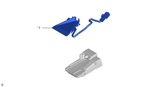
| *1 | FORWARD RECOGNITION WITH HEATER HOOD SUB-ASSEMBLY | - | - |
Removal
REMOVAL
PROCEDURE
1. REMOVE FORWARD RECOGNITION CAMERA
Click here .gif)
2. REMOVE FORWARD RECOGNITION WITH HEATER HOOD SUB-ASSEMBLY
NOTICE:
- Do not touch the inner surface of the forward recognition with heater hood sub-assembly.
- Do not apply force to the heating element of the forward recognition with heater hood sub-assembly or an open circuit may result.
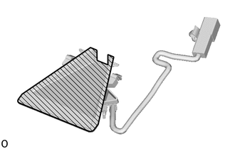
 | Inner Surface of Forward Recognition with Heater Hood Sub-assembly |
| (a) Disconnect the connector. NOTICE: When disconnecting the connector, do not forcibly pull the wire harness. |
|
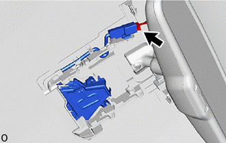
(b) Detach the connector clamp.
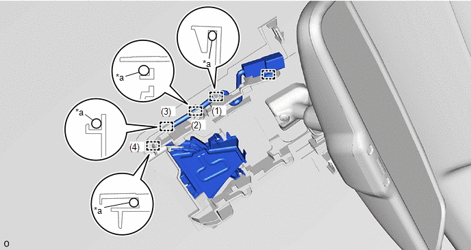
| *a | Wire Harness | - | - |
(c) Remove the wire harness from the guide in the order shown in the illustration.
NOTICE:
Do not pull the harness forcibly when remove the wire harness.
(d) Push the claw and pull the forward recognition with heater hood sub-assembly in the direction indicated by the arrow (1) in the illustration to detach the claw.
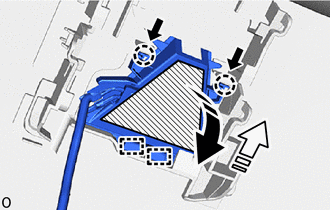
.png) | Push |
 | Remove in this Direction (1) |
 | Remove in this Direction (2) |
| | Heater Area |
NOTICE:
Do not press the heater area.
(e) Pull the forward recognition with heater hood sub-assembly in the direction indicated by the arrow (2) as shown in the illustration to detach the guide and remove the forward recognition with heater hood sub-assembly.
Installation
INSTALLATION
PROCEDURE
1. INSTALL FORWARD RECOGNITION WITH HEATER HOOD SUB-ASSEMBLY
NOTICE:
- Do not touch the inner surface of the forward recognition with heater hood sub-assembly.
- Do not apply force to the heating element of the forward recognition with heater hood sub-assembly or an open circuit may result.

.png) | Inner Surface of Forward Recognition with Heater Hood Sub-assembly |
(a) Insert the forward recognition with heater hood sub-assembly in the direction indicated by the arrow (1) as shown in the illustration to attach the guide.
.png) | Install in this Direction (1) |
.png) | Install in this Direction (2) |
| | Heater Area |
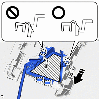
(b) Attach the claw in the direction indicated by the arrow (2) as shown in the illustration.
NOTICE:
- Make sure that the 2 claws are attached as shown in the illustration. Failure to do so may result in the malfunction of systems that use the forward recognition camera.
- Do not apply force to the heating element of the forward recognition with heater hood sub-assembly or an open circuit may result.
HINT:
Check the locking sound of the clip when attaching it.
(c) Install the wire harness to the guide in the order shown in the illustration.

| *a | Wire Harness | - | - |
(d) Attach the connector clamp to install the forward recognition with heater hood sub-assembly.
(e) Connect the connector.
2. INSTALL FORWARD RECOGNITION CAMERA
Click here .gif)
READ NEXT:
 Components
COMPONENTS ILLUSTRATION *1 CRUISE CONTROL MAIN SWITCH - - N*m (kgf*cm, ft.*lbf): Specified torque - -
Removal
REMOVAL PROCEDURE 1. REMOVE HORN BUTTON ASSEMBLY Click here 2. REMOVE CRUISE CONTROL MAIN SWITCH (a) Remove the 2 screws. *a Guide (b) Detach the guide. (c) Disconnect t
SEE MORE:
Installation
INSTALLATION PROCEDURE 1. INSTALL INSTRUMENT PANEL PASSENGER AIRBAG ASSEMBLY (a) Attach the 3 hooks on the side of the airbag door facing the front of the vehicle and set the instrument panel passenger airbag assembly onto the airbag door. *A Front of the Vehicle *B Rear of the Vehicle
Components
COMPONENTS ILLUSTRATION *A for 8 Speakers *B for 10 Speakers *C for 14 Speakers - - *1 REAR DOOR INSIDE HANDLE BEZEL PLUG LH *2 REAR DOOR TRIM BOARD SUB-ASSEMBLY LH *3 REAR DOOR TRIM COVER LH *4 REAR NO. 2 SPEAKER ASSEMBLY *5 REAR POWER WINDOW REGULATOR
