Lexus NX: Components
COMPONENTS
ILLUSTRATION
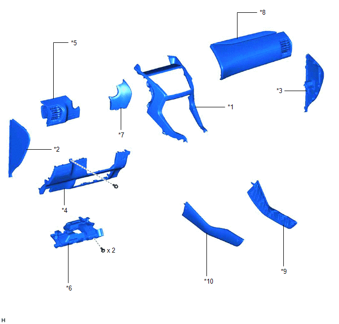
| *1 | CENTER INSTRUMENT CLUSTER FINISH PANEL ASSEMBLY | *2 | INSTRUMENT SIDE PANEL LH |
| *3 | INSTRUMENT SIDE PANEL RH | *4 | LOWER NO. 1 INSTRUMENT PANEL FINISH PANEL |
| *5 | NO. 1 INSTRUMENT PANEL SAFETY PAD SUB-ASSEMBLY | *6 | NO. 1 INSTRUMENT PANEL UNDER COVER SUB-ASSEMBLY |
| *7 | NO. 1 SWITCH HOLE BASE | *8 | NO. 2 INSTRUMENT PANEL SAFETY PAD SUB-ASSEMBLY |
| *9 | UPPER NO. 1 CONSOLE PANEL GARNISH | *10 | UPPER NO. 2 CONSOLE PANEL GARNISH |
ILLUSTRATION
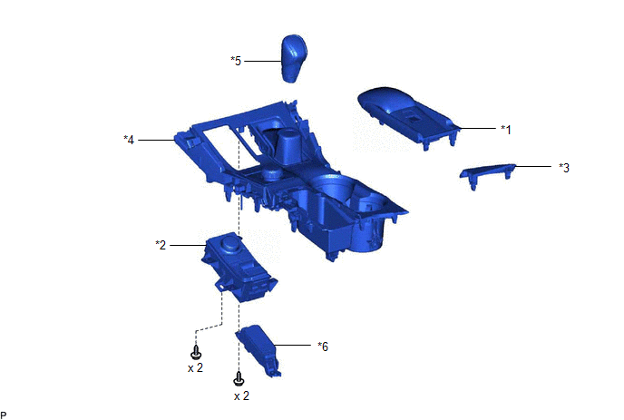
| *1 | CONSOLE ARMREST ASSEMBLY | *2 | INTEGRATION CONTROL AND PANEL ASSEMBLY (ABSORBER CONTROL SWITCH) |
| *3 | UPPER REAR CONSOLE PANEL | *4 | UPPER REAR CONSOLE PANEL SUB-ASSEMBLY |
| *5 | SHIFT LEVER KNOB SUB-ASSEMBLY | *6 | SHIFT POSITION INDICATOR |
READ NEXT:
 Removal
REMOVAL PROCEDURE 1. REMOVE CONSOLE ARMREST ASSEMBLY Click here 2. REMOVE UPPER REAR CONSOLE PANEL Click here 3. REMOVE UPPER NO. 2 CONSOLE PANEL GARNISH Click here 4. REMOVE UPPER NO. 1 CONSOLE
Inspection
INSPECTION PROCEDURE 1. INSPECT INTEGRATION CONTROL AND PANEL ASSEMBLY (ABSORBER CONTROL SWITCH) (a) Measure the resistance according to the value(s) in the table below. Standard Resistance: Te
Installation
INSTALLATION PROCEDURE 1. INSTALL INTEGRATION CONTROL AND PANEL ASSEMBLY (ABSORBER CONTROL SWITCH) (a) Install the integration control and panel assembly (absorber control switch) to the upper rear
SEE MORE:
Front Passenger Side Power Mirror cannot be Adjusted with Power Mirror Switch
DESCRIPTION When the outer mirror switch assembly mirror surface adjust switch (up/down/left/right) is operated, up/down/left/right signals are received by the main body ECU (multiplex network body ECU). The main body ECU (multiplex network body ECU) sends the received signals to the outer mirror co
Vehicles Speed Malfunction (B2624)
DESCRIPTION The multiplex tilt and telescopic ECU forms a network with the ECUs of other systems via CAN communication. Each ECU informs the other ECUs that it is connected to the network by sending a specified signal (periodic signal) onto the communication bus on a regular basis. The multiplex til
© 2016-2024 Copyright www.lexunx.com
