Lexus NX: Components
COMPONENTS
ILLUSTRATION
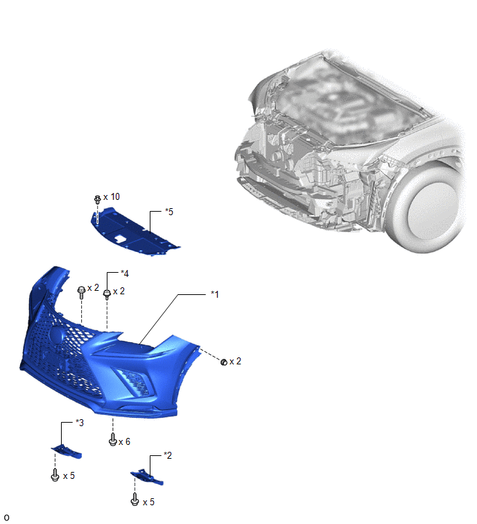
| *1 | FRONT BUMPER ASSEMBLY | *2 | FRONT FENDER FRONT SPLASH SHIELD LH |
| *3 | FRONT FENDER FRONT SPLASH SHIELD RH | *4 | RADIATOR GRILLE PROTECTOR |
| *5 | RADIATOR SUPPORT OPENING COVER | - | - |
ILLUSTRATION
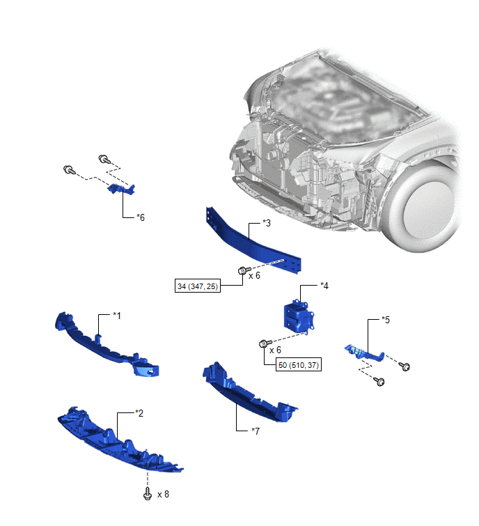
| *1 | FRONT BUMPER ENERGY ABSORBER | *2 | FRONT BUMPER LOWER ABSORBER |
| *3 | FRONT BUMPER REINFORCEMENT SUB-ASSEMBLY | *4 | FRONT BUMPER SIDE MOUNTING BRACKET ASSEMBLY LH |
| *5 | FRONT BUMPER SIDE RETAINER LH | *6 | FRONT BUMPER SIDE RETAINER RH |
| *7 | LOWER RADIATOR AIR GUIDE PLATE | - | - |
.png) | N*m (kgf*cm, ft.*lbf): Specified torque | - | - |
ILLUSTRATION
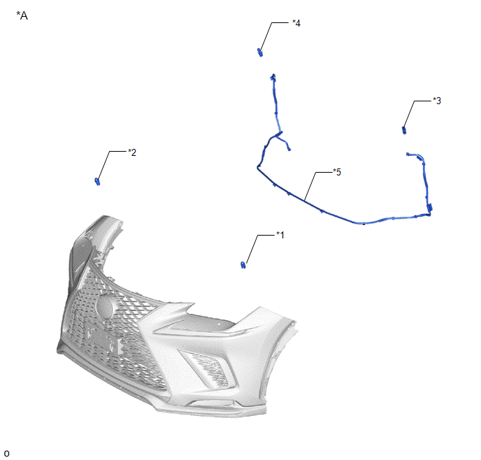
| *A | w/ Headlight Cleaner System | - | - |
| *1 | HEADLIGHT CLEANER WASHER NOZZLE COVER LH | *2 | HEADLIGHT CLEANER WASHER NOZZLE COVER RH |
| *3 | HEADLIGHT WASHER ACTUATOR SUB-ASSEMBLY LH | *4 | HEADLIGHT WASHER ACTUATOR SUB-ASSEMBLY RH |
| *5 | NO. 2 HEADLIGHT CLEANER HOSE | - | - |
ILLUSTRATION
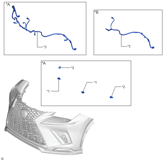
| *A | w/ Intuitive Parking Assist System | *B | w/o Intuitive Parking Assist System |
| *1 | FRONT CENTER ULTRASONIC SENSOR | *2 | FRONT CORNER ULTRASONIC SENSOR |
| *3 | NO. 3 ENGINE ROOM WIRE | - | - |
ILLUSTRATION
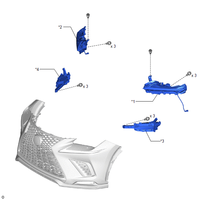
| *1 | CLEARANCE LIGHT ASSEMBLY LH | *2 | CLEARANCE LIGHT ASSEMBLY RH |
| *3 | FOG LIGHT ASSEMBLY LH | *4 | FOG LIGHT ASSEMBLY RH |
ILLUSTRATION
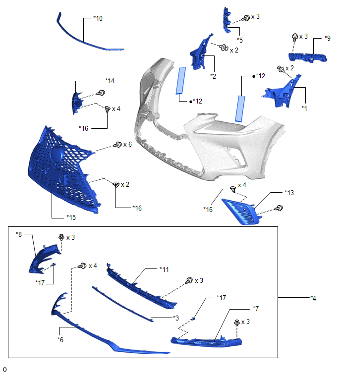
| *1 | AIR INTAKE DUCT LH | *2 | AIR INTAKE DUCT RH |
| *3 | FRONT BUMPER GUARD | *4 | FRONT BUMPER GUARD ASSEMBLY |
| *5 | FRONT BUMPER NO. 1 RETAINER BRACKET | *6 | FRONT BUMPER NO. 2 GUARD |
| *7 | FRONT BUMPER NO. 2 GUARD PAD LH | *8 | FRONT BUMPER NO. 2 GUARD PAD RH |
| *9 | FRONT BUMPER NO. 2 RETAINER BRACKET | *10 | HOOD TO FRONT END PANEL SEAL |
| *11 | LOWER RADIATOR GRILLE MOULDING | *12 | NO. 2 MOULDING TAPE |
| *13 | NO. 2 RADIATOR GRILLE GARNISH | *14 | RADIATOR GRILLE GARNISH |
| *15 | RADIATOR GRILLE SUB-ASSEMBLY | *16 | OUTSIDE MOULDING RETAINER |
| *17 | RETAINER | - | - |
| ● | Non-reusable part | - | - |
READ NEXT:
 Removal
REMOVAL CAUTION / NOTICE / HINT HINT: When the front bumper is damaged or deformed due to an accident or contact with other objects, etc., or the bumper installation area on the body is repaired, it i
Disassembly
DISASSEMBLY PROCEDURE 1. REMOVE HEADLIGHT WASHER ACTUATOR SUB-ASSEMBLY RH (w/ Headlight Cleaner System) Click here 2. REMOVE HEADLIGHT WASHER ACTUATOR SUB-ASSEMBLY LH (w/ Headlight Cleaner System) H
Reassembly
REASSEMBLY PROCEDURE 1. INSTALL NO. 2 MOULDING TAPE HINT:
When installing the No. 2 moulding tape, heat the front bumper cover and No. 2 moulding tape using a heat light.
Use the same procedure d
SEE MORE:
A/C Inverter Low Voltage Power Resource System Malfunction (B1477)
DESCRIPTION The compressor with motor assembly monitors the inverter control power voltage in the circuit. The hybrid vehicle control ECU stops the compressor control and stores this DTC when the monitored voltage is outside the specified range. This DTC will be stored as a history DTC. Compressor c
System Description
SYSTEM DESCRIPTION
The power steering system generates torque through the operation of the motor and the reduction gear installed on the column shaft in order to assist steering effort.
The power steering ECU assembly determines the direction and the amount of assist power in accordance with ve
