Lexus NX: Coolant
Replacement
REPLACEMENT
PROCEDURE
1. DRAIN ENGINE COOLANT
CAUTION:
Do not remove the reservoir cap while the engine assembly and radiator assembly are still hot. Pressurized, hot engine coolant and steam may be released and cause serious burns.
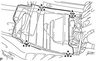
| (a) Detach the 4 clips and remove the rear engine under cover LH. |
|
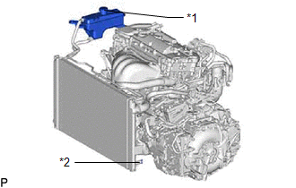
(b) Connect a hose with an inside diameter of 9 mm to the radiator drain cock.
| (c) Loosen the radiator drain cock plug and drain the engine coolant. HINT: Collect the engine coolant in a container and dispose of it according to the regulations in your area. |
|
(d) Remove the reservoir cap.
(e) Tighten the radiator drain cock plug by hand.
(f) Remove the vinyl tube from the radiator drain cock plug.
(g) Install the rear engine under cover LH with the 4 clips.
2. ADD ENGINE COOLANT
CAUTION:
Do not remove the reservoir cap while the engine and radiator are still hot. Pressurized, hot engine coolant and steam may be released and cause serious burns.
(a) Add engine coolant to the radiator reservoir assembly filler opening until it is filled to the B line at the base of the radiator reservoir filler neck.
Standard capacity:
6.9 liters (7.3 US qts, 6.1 Imp.qts)
NOTICE:
Never use water as a substitute for engine coolant.
HINT:
- The B line is the lower edge of the inner wall of the filler neck.
- TOYOTA vehicles are filled with TOYOTA SLLC at the factory. In order to avoid damage to the engine cooling system and other technical problems, only use TOYOTA SLLC or similar high quality ethylene glycol based non-silicate, non-amine, non-nitrite, non-borate coolant with long-life hybrid organic acid technology (coolant with long-life hybrid organic acid technology consists of a combination of low phosphates and organic acids).
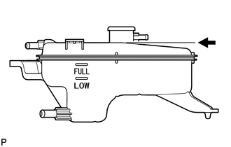
 | B Line |
(b) Press the No. 1 radiator hose and No. 2 radiator hose several times by hand, and then check the level of the coolant. If the coolant level drops below the B line, add coolant to the B line.
(c) Install the reservoir cap.
(d) Put the engine in inspection mode (maintenance mode).
Click here 
(e) Start the engine and warm it up until the engine coolant level of the radiator reservoir assembly has stabilized.
CAUTION:
- Wear protective gloves.
- Be careful as the radiator hoses are hot.
- Keep your hands away from the cooling fan.
NOTICE:
- Perform the engine speed with 2000 rpm or less.
- Make sure that the radiator reservoir still has some engine coolant in it.
- After starting the engine, if the radiator reservoir does not have any engine coolant, perform the following: 1) stop the engine, 2) wait until the engine coolant has cooled down, and 3) add engine coolant until the engine coolant is filled to the B line.
- If there is not enough engine coolant, the engine may burn out or overheat.
- Pay attention to the needle of the engine coolant temperature meter. Make sure that the needle does not show an abnormally high temperature.
(f) Stop the engine and wait until the coolant cools down to ambient temperature.
(g) Check that the engine coolant level is between the FULL and LOW line.
If the engine coolant level is below the LOW line, repeat all of the procedures above.
If the engine coolant level is above the FULL line, drain engine coolant so that the engine coolant level is between the FULL and LOW line.
3. INSPECT FOR COOLANT LEAK
Click here
READ NEXT:
 Cooling Fan Ecu
On-vehicle InspectionON-VEHICLE INSPECTION PROCEDURE 1. INSPECT COOLING FAN ECU (a) Check and ensure the following conditions: (1) The power switch is off. (2) The engine coolant temperature is less
Components
COMPONENTS ILLUSTRATION *1 COOLING FAN ECU *2 COOLING FAN MOTOR *3 COOLING FAN WIRE *4 FAN *5 NO. 2 COOLING FAN MOTOR *6 NO. 2 FAN *7 COOLING FAN MOTOR INSULATOR
SEE MORE:
Removal
REMOVAL CAUTION / NOTICE / HINT HINT:
Use the same procedure for the RH and LH sides.
The procedure described below is for the LH side.
PROCEDURE 1. REMOVE FRONT BUMPER ASSEMBLY Click here 2. REMOVE FOG LIGHT ASSEMBLY LH (a) Remove the 2 screws. (b) Detach the guide and remo
Diagnosis System
DIAGNOSIS SYSTEM DIAGNOSIS MODE FUNCTION (a) w/ Lane Centering Function: When a malfunction occurs in the lane tracing assist system system, the LTA indicator light illuminates yellow and a message is displayed on the multi-information display. Warning Message Details DTC/RoB LTA Indicator
