Lexus NX: Disassembly
DISASSEMBLY
PROCEDURE
1. REMOVE INTAKE VALVE
| (a) Using SST and wooden blocks, compress the inner compression spring and remove the valve spring retainer locks. SST: 09202-70020 SST: 09202-00021 |
|
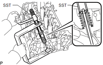
(b) Remove the valve spring retainer, inner compression spring and intake valve.
HINT:
Arrange the removed parts in the correct order.
2. REMOVE EXHAUST VALVE
| (a) Using SST and wooden blocks, compress the inner compression spring and remove the valve spring retainer locks. SST: 09202-70020 SST: 09202-00021 |
|
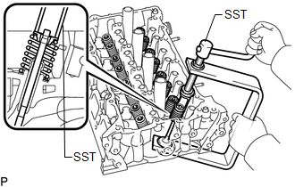
(b) Remove the valve spring retainer, inner compression spring and exhaust valve.
HINT:
Arrange the removed parts in the correct order.
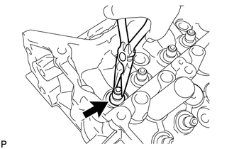
3. REMOVE VALVE STEM OIL SEAL
| (a) Using needle-nose pliers, remove the valve stem oil seals. |
|
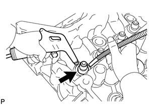
4. REMOVE VALVE SPRING SEAT
| (a) Using compressed air and a magnet hand, remove the valve spring seat by blowing air onto it. |
|
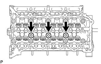
5. REMOVE NO. 1 STRAIGHT SCREW PLUG
NOTICE:
If coolant leaks from a No. 1 straight screw plug or a plug is corroded, replace it.
| (a) Using a 10 mm hexagon wrench, remove the 3 No. 1 straight screw plugs and 3 gaskets. |
|
6. REMOVE NO. 2 STRAIGHT SCREW PLUG
NOTICE:
If coolant leaks from a No. 2 straight screw plug or the plug is corroded, replace it.
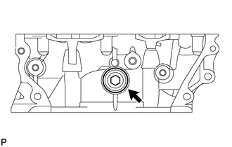
(a) Using a 14 mm hexagon wrench, remove the No. 2 straight screw plug and gasket.
7. REMOVE CYLINDER HEAD STUD BOLT
NOTICE:
If a stud bolt is deformed or its threads are damaged, replace it.
READ NEXT:
 Inspection
INSPECTION PROCEDURE 1. INSPECT CYLINDER HEAD SUB-ASSEMBLY (a) Using a precision straightedge and feeler gauge, measure the warpage of the contact surfaces where the cylinder head contacts the cylinde
Replacement
REPLACEMENT PROCEDURE 1. REPLACE INTAKE VALVE GUIDE BUSH (a) Heat the cylinder head sub-assembly to approximately 80 to 100°C (176 to 212°F). (b) Place the cylinder head sub-assembly on wooden block
Reassembly
REASSEMBLY CAUTION / NOTICE / HINT HINT: Perform "Inspection After Repairs" after replacing the cylinder head sub-assembly. Click here PROCEDURE 1. INSTALL CYLINDER HEAD STUD BOLT NOTICE: If a stud
SEE MORE:
Removal
REMOVAL PROCEDURE 1. REMOVE STEERING WHEEL ASSEMBLY Click here 2. REMOVE STEERING PAD SWITCH ASSEMBLY Click here 3. REMOVE CRUISE CONTROL MAIN SWITCH Click here 4. REMOVE SHIFT PADDLE SWITCH (TRANSMISSION SHIFT SWITCH ASSEMBLY) Click here 5. REMOVE STEERING WHEEL HEATER CONTROL ASSEMBLY (
No. 2 Clearance Warning Buzzer Circuit
DESCRIPTION This circuit consists of the No. 2 clearance warning buzzer and clearance warning ECU assembly. An ECU-excited type buzzer is used. The ECU operates the buzzers using a sound pattern that changes depending on the distance to the obstacle. WIRING DIAGRAM PROCEDURE 1. PERFORM ACTIVE
