Lexus NX: Disassembly
DISASSEMBLY
PROCEDURE
1. REMOVE HEADLIGHT WASHER ACTUATOR SUB-ASSEMBLY RH (w/ Headlight Cleaner System)
Click here .gif)
2. REMOVE HEADLIGHT WASHER ACTUATOR SUB-ASSEMBLY LH (w/ Headlight Cleaner System)
HINT:
Use the same procedure described for the RH side.
3. REMOVE HEADLIGHT CLEANER WASHER NOZZLE COVER RH (w/ Headlight Cleaner System)
Click here
4. REMOVE HEADLIGHT CLEANER WASHER NOZZLE COVER LH (w/ Headlight Cleaner System)
HINT:
Use the same procedure described for the RH side.
5. REMOVE NO. 2 HEADLIGHT CLEANER HOSE (w/ Headlight Cleaner System)
Click here
6. REMOVE HEADLIGHT CLEANER WASHER BRACKET (w/ Headlight Cleaner System)
Click here
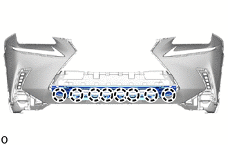
7. REMOVE NO. 3 ENGINE ROOM WIRE
(a) Disconnect the millimeter wave radar sensor connector.
(b) w/ Intuitive Parking Assist System:
Disconnect the 4 connectors.
(c) w/ Panoramic View Monitor System:
Disconnect the connector.
(d) w/o Intuitive Parking Assist System:
Detach the 6 clamps and remove the No. 3 engine room wire.
(e) w/ Intuitive Parking Assist System:
Detach the 12 clamps and remove the No. 3 engine room wire.
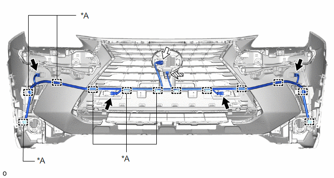
| *A | w/o Intuitive Parking Assist System | - | - |
.png) | w/ Intuitive Parking Assist System | .png) | Millimeter Wave Radar Sensor Connector |
.png) | w/ Panoramic View Monitor System | - | - |
8. REMOVE FRONT CORNER ULTRASONIC SENSOR (w/ Intuitive Parking Assist System)
Click here
9. REMOVE FRONT CORNER ULTRASONIC SENSOR RETAINER (w/ Intuitive Parking Assist System)
Click here
10. REMOVE FRONT CENTER ULTRASONIC SENSOR (w/ Intuitive Parking Assist System)
Click here
11. REMOVE CLEARANCE LIGHT ASSEMBLY LH
(a) for LED Type Turn Signal Light:
Click here
(b) for Bulb Type Turn Signal Light:
Click here
12. REMOVE CLEARANCE LIGHT ASSEMBLY RH
HINT:
Use the same procedure described for the LH side.
13. REMOVE FOG LIGHT ASSEMBLY LH
Click here
14. REMOVE FOG LIGHT ASSEMBLY RH
HINT:
Use the same procedure described for the LH side.
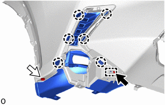
15. REMOVE FRONT BUMPER NO. 2 RETAINER BRACKET
| (a) Remove the 3 screws. |
|
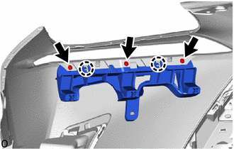
(b) Detach the 2 claws and remove the front bumper No. 2 retainer bracket.
16. REMOVE FRONT BUMPER NO. 1 RETAINER BRACKET
HINT:
Use the same procedure described for the front bumper No. 2 retainer bracket.
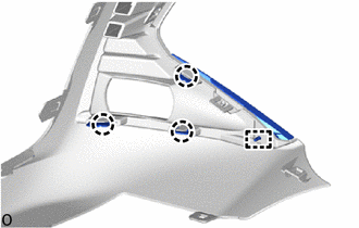
17. REMOVE AIR INTAKE DUCT LH
| (a) Remove the 2 clips. |
|
(b) Detach the 2 guides and remove the air intake duct LH.
18. REMOVE AIR INTAKE DUCT RH
HINT:
Use the same procedure described for the LH side.
19. REMOVE HOOD TO FRONT END PANEL SEAL
| (a) Detach the 13 clips and remove the hood to front end panel seal. |
|
20. REMOVE RADIATOR GRILLE SUB-ASSEMBLY
Click here
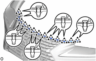
21. REMOVE LOWER RADIATOR GRILLE
| (a) Detach the 8 claws and remove the lower radiator grille. |
|
22. REMOVE NO. 2 RADIATOR GRILLE GARNISH
(a) Using screwdriver, remove the retainer.
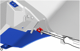
.png) | Protective Tape |
HINT:
Tape the screwdriver tip before use.
(b) Remove the screw.
| | Screw |
| | Clip |
(c) Remove the clip.
(d) Detach the 6 claws and guide and remove the No. 2 radiator grille garnish.
23. REMOVE RADIATOR GRILLE GARNISH
HINT:
Use the same procedure described for the No. 2 radiator grille garnish.
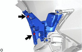
24. REMOVE FOG LIGHT BRACKET LH
| (a) Detach the 3 claws, guide and remove the fog light bracket LH. |
|
25. REMOVE FOG LIGHT BRACKET RH
HINT:
Use the same procedure described for the LH side.
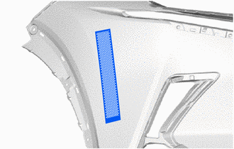
26. REMOVE NO. 2 MOULDING TAPE
HINT:
- When removing the No. 2 moulding tape, heat the front bumper cover and No. 2 moulding tape using a heat light.
- Use the same procedure described for the other side.
Standard:
| Item | Temperature |
|---|---|
| Front Bumper Cover | 20 to 30°C (68 to 86°F) |
| No. 2 Moulding Tape | 20 to 30°C (68 to 86°F) |
NOTICE:
Do not heat the front bumper cover and No. 2 moulding tape excessively.
| (a) Remove the No. 2 moulding tape. |
|
READ NEXT:
 Reassembly
REASSEMBLY PROCEDURE 1. INSTALL NO. 2 MOULDING TAPE HINT:
When installing the No. 2 moulding tape, heat the front bumper cover and No. 2 moulding tape using a heat light.
Use the same procedure d
Installation
INSTALLATION CAUTION / NOTICE / HINT HINT: A bolt without a torque specification is shown in the standard bolt chart. Click here PROCEDURE 1. INSTALL FRONT BUMPER SIDE RETAINER LH (a) Attach the
SEE MORE:
Thermostat
ComponentsCOMPONENTS ILLUSTRATION *1 THERMOSTAT *2 WATER INLET *3 GASKET - - N*m (kgf*cm, ft.*lbf): Specified torque ● Non-reusable part RemovalREMOVAL PROCEDURE 1. DRAIN ENGINE COOLANT Click here 2. DISCONNECT WATER INLET (a) Remove the 2 nuts and disconne
Checking and replacing fuses
If any of the electrical components
do not operate, a fuse may have
blown. If this happens, check and
replace the fuses as necessary.
Checking and replacing fuses
1. Turn the power switch off.
2. Open the fuse box cover.
Engine compartment: type A fuse
box
Push the tab in and lift the lid
