Lexus NX: Door Control Switch
Components
COMPONENTS
ILLUSTRATION
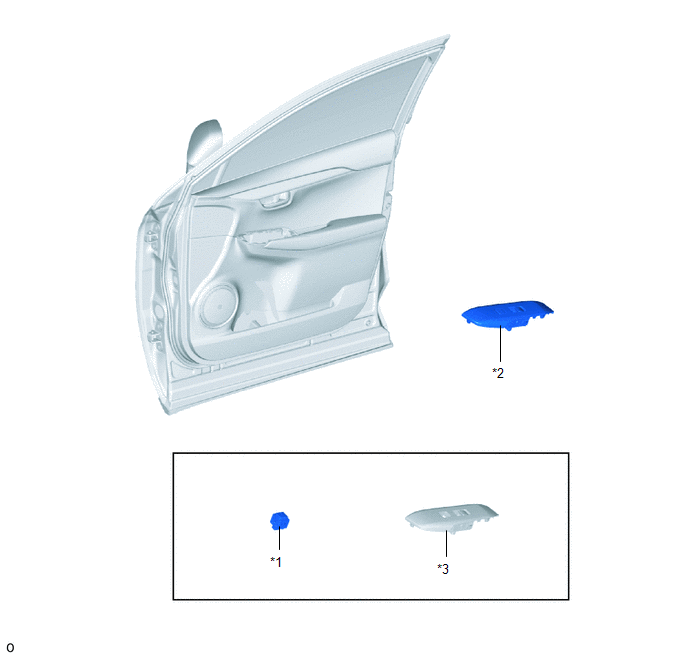
| *1 | DOOR CONTROL SWITCH ASSEMBLY | *2 | POWER WINDOW REGULATOR SWITCH ASSEMBLY WITH FRONT DOOR ARMREST BASE PANEL |
| *3 | FRONT DOOR ARMREST BASE PANEL | - | - |
Removal
REMOVAL
CAUTION / NOTICE / HINT
HINT:
- Use the same procedure for RHD and LHD vehicles.
- The procedure listed below is for LHD vehicles.
PROCEDURE
1. REMOVE POWER WINDOW REGULATOR SWITCH ASSEMBLY WITH FRONT DOOR ARMREST BASE PANEL
Click here .gif)
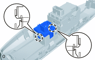
2. REMOVE DOOR CONTROL SWITCH ASSEMBLY
| (a) Detach the 2 claws and remove the door control switch assembly. |
|
Inspection
INSPECTION
PROCEDURE
1. INSPECT DOOR CONTROL SWITCH ASSEMBLY
| (a) Measure the resistance according to the value(s) in the table below. Standard Resistance:
If the result is not as specified, replace the door control switch assembly. |
|
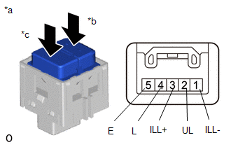
(b) Check that the LED illuminates.
(1) Apply battery voltage to the door control switch assembly and check that the LED illuminates.
OK:
| Measurement Condition | Specified Condition |
|---|---|
| Battery positive (+) → 3 (ILL+) Battery negative (-) → 1 (ILL-) | LED illuminates |
If the result is not as specified, replace the door control switch assembly.
Installation
INSTALLATION
CAUTION / NOTICE / HINT
HINT:
- Use the same procedure for RHD and LHD vehicles.
- The procedure listed below is for LHD vehicles.
PROCEDURE
1. INSTALL DOOR CONTROL SWITCH ASSEMBLY
(a) Attach the 2 claws to install the door control switch assembly.
2. INSTALL POWER WINDOW REGULATOR SWITCH ASSEMBLY WITH FRONT DOOR ARMREST BASE PANEL
Click here .gif)
READ NEXT:
 Components
COMPONENTS ILLUSTRATION *1 TRANSMITTER BATTERY *2 DOOR CONTROL TRANSMITTER HOUSING SET *3 TRANSMITTER BATTERY HOLDER *4 MECHANICAL KEY *5 ELECTRICAL TRANSMITTER SUB-ASSEMBLY
Removal
REMOVAL PROCEDURE 1. REMOVE TRANSMITTER BATTERY Click here 2. REMOVE TRANSMITTER (CARD KEY) BATTERY Click here
SEE MORE:
System Diagram
SYSTEM DIAGRAM SYSTEM DIAGRAM (a) The CAN communication system is composed of 5 buses. CAN Main Bus Line Terminating Resistor CAN Branch Line * Gateway Function Equipped ECU Bus Monitoring Direction - - Connected to Code ECU/Sensor Name CAN DTC Storage
Vehicles Speed Malfunction (B2624)
DESCRIPTION The multiplex tilt and telescopic ECU forms a network with the ECUs of other systems via CAN communication. Each ECU informs the other ECUs that it is connected to the network by sending a specified signal (periodic signal) onto the communication bus on a regular basis. The multiplex til
