Lexus NX: Drive Motor "A" Position Sensor Angle Malfunction (P1CAD-168,P1CB0-795,P1CB3-796)
DESCRIPTION
The MG ECU, which is built into the inverter with converter assembly, monitors its internal operation and detects malfunctions.
HINT:
The term "drive motor A" indicates the motor (MG2).
| DTC No. | Detection Item | DTC Detection Condition | Trouble Area | MIL | Warning Indicate |
|---|---|---|---|---|---|
| P1CAD-168 | Drive Motor "A" Position Sensor Angle Malfunction | Motor resolver angle malfunction: The difference between the resolver angle for control and estimated resolver angle exceeds the allowable limit. (1 trip detection logic) |
| Comes on | Master Warning Light: Comes on |
| P1CB0-795 | Drive Motor "A" Position Sensor REF Signal Cycle Malfunction | Resolver REF signal cycle malfunction: Excitation signal (REF signal) for resolver angle detection cycle malfunction (1 trip detection logic) |
| Comes on | Master Warning Light: Comes on |
| P1CB3-796 | Drive Motor "A" Position Sensor REF Signal Stop Malfunction | Resolver REF signal oscillation stop malfunction: An error is detected when the excitation signal (REF signal) for resolver angle detection is not detected. (1 trip detection logic) |
| Comes on | Master Warning Light: Comes on |
| DTC No. | Data List |
|---|---|
| P1CAD-168 | Motor (MG2) Revolution |
| P1CB0-795 | |
| P1CB3-796 |
MONITOR DESCRIPTION
The MG ECU (in the inverter with converter assembly) performs many diagnostic tests to verify proper operation of internal ECU systems. In one of these tests, the MG ECU checks for an R/D (Resolver/Digital converter) malfunction involving the motor resolver. If the MG ECU detects an R/D converter error, it will conclude that there is an internal malfunction involving the motor resolver and the hybrid vehicle control ECU will illuminate the MIL and store a DTC.
MONITOR STRATEGY
| Related DTCs | P1CAD (INF 168): R/D converter resolver angle abnormality P1CB0 (INF 795): REF malfunction (frequency abnormality) P1CB3 (INF 796): REF malfunction (REF Signal abnormality) |
| Required sensors/components | Inverter with converter assembly (MG ECU) |
| Frequency of operation | Continuous |
| Duration | TMC's intellectual property |
| MIL operation | 1 driving cycle |
| Sequence of operation | None |
TYPICAL ENABLING CONDITIONS
| The monitor will run whenever the following DTCs are not stored | TMC's intellectual property |
| Other conditions belong to TMC's intellectual property | - |
TYPICAL MALFUNCTION THRESHOLDS
| TMC's intellectual property | - |
COMPONENT OPERATING RANGE
| Hybrid vehicle control ECU | DTC P1CAD (INF 168) is not detected DTC P1CB0 (INF 795) is not detected DTC P1CB3 (INF 796) is not detected |
CONFIRMATION DRIVING PATTERN
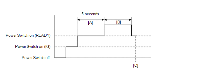
- Connect the Techstream to the DLC3.
- Turn the power switch on (IG) and turn the Techstream on.
- Clear the DTCs (even if no DTCs are stored, perform the clear DTC procedure).
- Turn the power switch off and wait for 30 seconds or more.
- Turn the power switch on (IG) and wait for 5 seconds or more.
- Turn the power switch on (READY) with the shift lever in P and wait for 5 seconds or more. [A]
- Drive the vehicle at 5 km/h (3 mph) or more for 5 seconds or more. [B]
- Enter the following menus: Powertrain / Hybrid Control / Trouble Codes. [C]
-
Read the current DTCs.
HINT:
- If a current DTC is output, the system is malfunctioning.
- If current DTCs are not output, check for permanent DTCs.
- Check that the permanent DTCs are cleared.
- If the permanent DTCs are not cleared, perform the universal trip, and then check for permanent DTCs again.
WIRING DIAGRAM
Refer to the wiring diagram for DTC P1CAC-200.
Click here .gif)
CAUTION / NOTICE / HINT
CAUTION:
- Before inspecting the high-voltage system or disconnecting the low voltage connector of the inverter with converter assembly, take safety precautions such as wearing insulated gloves and removing the service plug grip to prevent electrical shocks. After removing the service plug grip, put it in your pocket to prevent other technicians from accidentally reconnecting it while you are working on the high-voltage system.
-
After removing the service plug grip, wait for at least 10 minutes before touching any of the high-voltage connectors or terminals. After waiting for 10 minutes, check the voltage at the terminals in the inspection point in the inverter with converter assembly. The voltage should be 0 V before beginning work.
Click here
HINT:
Waiting for at least 10 minutes is required to discharge the high-voltage capacitor inside the inverter with converter assembly.
NOTICE:
After turning the power switch off, waiting time may be required before disconnecting the cable from the negative (-) auxiliary battery terminal. Therefore, make sure to read the disconnecting the cable from the negative (-) auxiliary battery terminal notices before proceeding with work.
Click here
HINT:
-
If DTC P1CAD-168 is output, clear the DTCs, perform the following procedure, and check that the same DTC is not output after the repair.
- Turn the power switch on (READY).
- Drive the vehicle at 5 km/h (3 mph) or more for 5 seconds or more.
-
If DTC P1CB0-795 or P1CB3-796 is output, clear the DTCs, perform the following procedure, and check that the same DTC is not output after the repair.
- Turn the power switch on (IG) and wait for 5 seconds or more.
- When a resolver signal malfunction exists, the vehicle may not drive smoothly.
PROCEDURE
| 1. | CHECK DTC OUTPUT (HYBRID CONTROL) |
(a) Connect the Techstream to the DLC3.
(b) Turn the power switch on (IG).
(c) Enter the following menus: Powertrain / Hybrid Control / Trouble Codes.
(d) Check for DTCs.
Powertrain > Hybrid Control > Trouble Codes| Result | Proceed to |
|---|---|
| P1CAD-168, P1CB0-795 or P1CB3-796 only is output, or DTCs except the ones in the table below are also output. | A |
| Any of the following DTCs are also output. | B |
| Relevant DTC | |
|---|---|
| P0A3F-243 | Drive Motor "A" Position Sensor Circuit |
| P0A40-500 | Drive Motor "A" Position Sensor Circuit Range / Performance |
| P0A41-245 | Drive Motor "A" Position Sensor Circuit Low |
| P0A45-669 | Drive Motor "B" Position Sensor Circuit |
| P0A4B-253 | Generator Position Sensor Circuit |
(e) Turn the power switch off.
| B | .gif) | GO TO DTC CHART (HYBRID CONTROL SYSTEM) |
|
.gif)
| 2. | CHECK CONNECTOR CONNECTION CONDITION (INVERTER WITH CONVERTER ASSEMBLY CONNECTOR) |
Click here
| Result | Proceed to |
|---|---|
| OK | A |
| NG (The connector is not connected securely.) | B |
| NG (The terminals are not making secure contact or are deformed, or water or foreign matter exists in the connector.) | C |
| B | | CONNECT SECURELY |
| C | | REPAIR OR REPLACE HARNESS OR CONNECTOR |
|
| 3. | CHECK HARNESS AND CONNECTOR (INVERTER WITH CONVERTER ASSEMBLY - GENERATOR RESOLVER) |
Click here
| NG | | REPAIR OR REPLACE HARNESS OR CONNECTOR |
|
| 4. | CHECK GENERATOR RESOLVER |
Click here
| NG | | GO TO STEP 12 |
|
| 5. | CHECK HARNESS AND CONNECTOR (INVERTER WITH CONVERTER ASSEMBLY - MOTOR RESOLVER) |
Click here
| NG | | REPAIR OR REPLACE HARNESS OR CONNECTOR |
|
| 6. | CHECK MOTOR RESOLVER |
Click here
| NG | | GO TO STEP 14 |
|
| 7. | CHECK HARNESS AND CONNECTOR (INVERTER WITH CONVERTER ASSEMBLY - REAR MOTOR RESOLVER) |
Click here
| NG | | REPAIR OR REPLACE HARNESS OR CONNECTOR |
|
| 8. | CHECK REAR MOTOR RESOLVER |
Click here
| NG | | GO TO STEP 16 |
|
| 9. | CHECK CONNECTOR CONNECTION CONDITION (GENERATOR RESOLVER CONNECTOR) |
Click here
| Result | Proceed to |
|---|---|
| OK | A |
| NG (The connector is not connected securely.) | B |
| NG (The terminals are not making secure contact or are deformed, or water or foreign matter exists in the connector.) | C |
| B | | CONNECT SECURELY |
| C | | REPAIR OR REPLACE HARNESS OR CONNECTOR |
|
| 10. | CHECK CONNECTOR CONNECTION CONDITION (MOTOR RESOLVER CONNECTOR) |
Click here
| Result | Proceed to |
|---|---|
| OK | A |
| NG (The connector is not connected securely.) | B |
| NG (The terminals are not making secure contact or are deformed, or water or foreign matter exists in the connector.) | C |
| B | | CONNECT SECURELY |
| C | | REPAIR OR REPLACE HARNESS OR CONNECTOR |
|
| 11. | CHECK CONNECTOR CONNECTION CONDITION (REAR MOTOR RESOLVER CONNECTOR) |
Click here
| Result | Proceed to |
|---|---|
| OK | A |
| NG (The connector is not connected securely.) | B |
| NG (The terminals are not making secure contact or are deformed, or water or foreign matter exists in the connector.) | C |
| A | | REPLACE INVERTER WITH CONVERTER ASSEMBLY |
| B | | CONNECT SECURELY |
| C | | REPAIR OR REPLACE HARNESS OR CONNECTOR |
| 12. | CHECK CONNECTOR CONNECTION CONDITION (GENERATOR RESOLVER CONNECTOR) |
Click here
| Result | Proceed to |
|---|---|
| OK | A |
| NG (The connector is not connected securely.) | B |
| NG (The terminals are not making secure contact or are deformed, or water or foreign matter exists in the connector.) | C |
| B | | CONNECT SECURELY |
| C | | REPAIR OR REPLACE HARNESS OR CONNECTOR |
|
| 13. | INSPECT HYBRID VEHICLE TRANSAXLE ASSEMBLY (GENERATOR RESOLVER) |
Click here
| OK | | REPAIR OR REPLACE HARNESS OR CONNECTOR |
| NG | | REPLACE HYBRID VEHICLE TRANSAXLE ASSEMBLY |
| 14. | CHECK CONNECTOR CONNECTION CONDITION (MOTOR RESOLVER CONNECTOR) |
Click here
| Result | Proceed to |
|---|---|
| OK | A |
| NG (The connector is not connected securely.) | B |
| NG (The terminals are not making secure contact or are deformed, or water or foreign matter exists in the connector.) | C |
| B | | CONNECT SECURELY |
| C | | REPAIR OR REPLACE HARNESS OR CONNECTOR |
|
| 15. | INSPECT HYBRID VEHICLE TRANSAXLE ASSEMBLY (MOTOR RESOLVER) |
Click here
| OK | | REPAIR OR REPLACE HARNESS OR CONNECTOR |
| NG | | REPLACE HYBRID VEHICLE TRANSAXLE ASSEMBLY |
| 16. | CHECK CONNECTOR CONNECTION CONDITION (REAR MOTOR RESOLVER CONNECTOR) |
Click here
| Result | Proceed to |
|---|---|
| OK | A |
| NG (The connector is not connected securely.) | B |
| NG (The terminals are not making secure contact or are deformed, or water or foreign matter exists in the connector.) | C |
| B | | CONNECT SECURELY |
| C | | REPAIR OR REPLACE HARNESS OR CONNECTOR |
|
| 17. | INSPECT REAR TRACTION MOTOR WITH TRANSAXLE ASSEMBLY (REAR MOTOR RESOLVER) |
Click here
| OK | | REPAIR OR REPLACE HARNESS OR CONNECTOR |
| NG | | REPLACE REAR TRACTION MOTOR WITH TRANSAXLE ASSEMBLY |
READ NEXT:
 Drive Motor "B" Position Sensor Angle Malfunction (P1CAE-715,P1CB1-798,P1CB4-799)
DESCRIPTION The inverter with converter assembly (MG ECU) monitors its internal operation and detects malfunctions. DTC No. Detection Item DTC Detection Condition Trouble Area MIL Warning
Throttle / Pedal Position Sensor / Switch "D" Circuit (P2120-152,...,P2138-154)
DESCRIPTION The accelerator pedal position sensor is mounted on the accelerator pedal to detect how much the pedal is depressed. This is a non-contact sensor with Hall elements. There are 2 outputs fr
Barometric Pressure Sensor "A" Circuit Low (P2228-268,P2229-269)
DESCRIPTION Refer to the description for DTC P0069-273. Click here DTC No. Detection Item DTC Detection Condition Trouble Area MIL Warning Indicate P2228-268 Barometric Pressure
SEE MORE:
ECU Malfunction (B1003)
DESCRIPTION DTC No. Detection Item DTC Detection Condition Trouble Area DTC Output from B1003 ECU Malfunction A malfunction in the non-volatile storage of the central gateway ECU (network gateway ECU) is detected. Central gateway ECU (network gateway ECU) Central gateway ECU (
Installation
INSTALLATION PROCEDURE 1. INSTALL MAP LIGHT ASSEMBLY (PERSONAL LIGHT) (a) Connect the connectors. (b) Attach the 4 clips to install the map light assembly (personal light).
