Lexus NX: Electric Parking Brake AUTO Indicator Light Circuit
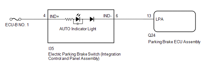
WIRING DIAGRAM
CAUTION / NOTICE / HINT
NOTICE:
- Inspect the fuses for circuits related to this system before performing the following inspection procedure.
- Before disconnecting connectors or fuses, turn the power switch off and wait 20 seconds or more.
- When replacing the parking brake ECU assembly, operate the electric parking brake switch (integration control and panel assembly), as the parking brake indicator light (red) blinks when the power switch is first turned on (IG).
PROCEDURE
| 1. | READ VALUE USING TECHSTREAM (AUTO MODE) |
(a) Turn the power switch off.
(b) Connect the Techstream to the DLC3.
(c) Turn the power switch on (IG) and the Techstream on.
(d) Enter the following menus: Chassis / Electric Parking Brake / Data List.
(e) Check the values by referring to the table below.
Chassis > Electric Parking Brake > Data List| Tester Display | Measurement Item | Range | Normal Condition |
|---|---|---|---|
| Auto Mode | AUTO (shift-linked) mode permission display | ON or OFF | ON: AUTO (shift-linked) mode OFF: Manual mode |
| Tester Display |
|---|
| Auto Mode |
(f) When switching the mode, check that the Data List display turns on and off.
HINT:
For details regarding mode switching: Click here .gif)
| Result | Proceed to |
|---|---|
| AUTO indicator light does not illuminate and turn off according to turning Active Test on and off | A |
| AUTO indicator light illuminates and turns off according to turning Active Test on and off | B |
| B | .gif) | GO TO STEP 5 |
|
.gif)
| 2. | CHECK DTC |
(a) Check for DTCs.
Click here
| DTC is output | | GO TO DIAGNOSTIC TROUBLE CODE CHART |
|
| 3. | INSPECT ELECTRIC PARKING BRAKE SWITCH (INTEGRATION CONTROL AND PANEL ASSEMBLY) |
(a) Remove the electric parking brake switch (integration control and panel assembly).
Click here
(b) Inspect the electric parking brake switch (integration control and panel assembly).
Click here
| NG | | REPLACE INTEGRATION CONTROL AND PANEL ASSEMBLY |
|
| 4. | CHECK HARNESS AND CONNECTOR (PARKING BRAKE ECU ASSEMBLY - ELECTRIC PARKING BRAKE SWITCH (INTEGRATION CONTROL AND PANEL ASSEMBLY)) |
(a) Disconnect the I35 electric parking brake switch (integration control and panel assembly) connector.
(b) Disconnect the Q24 parking brake ECU assembly connector.
(c) Measure the resistance according to the value(s) in the table below.
Standard Resistance:
| Tester Connection | Condition | Specified Condition |
|---|---|---|
| Q24-20 (LCK1) - I35-9 (LOK1) | Always | Below 5 Ω |
| Q24-15 (LCK2) - I35-10 (LOK2) | Always | Below 5 Ω |
| Q24-20 (LCK1) or I35-9 (LOK1) - Body ground | Always | 10 kΩ or higher |
| Q24-15 (LCK2) or I35-10 (LOK2) - Body ground | Always | 10 kΩ or higher |
| Q24-19 (REL1) - I35-1 (RLS1) | Always | Below 5 Ω |
| Q24-16 (REL2) - I35-2 (RLS2) | Always | Below 5 Ω |
| Q24-19 (REL1) or I35-1 (RLS1) - Body ground | Always | 10 kΩ or higher |
| Q24-16 (REL2) or I35-2 (RLS2) - Body ground | Always | 10 kΩ or higher |
| I35-16 (GND1) - Body ground | Always | Below 5 Ω |
| NG | | REPAIR OR REPLACE HARNESS OR CONNECTOR |
|
| 5. | PERFORM ACTIVE TEST USING TECHSTREAM (AUTO LIGHT) |
(a) Turn the power switch off.
(b) Connect the Techstream to the DLC3.
(c) Turn the power switch on (IG) and the Techstream on.
(d) Enter the following menus: Chassis / Electric Parking Brake / Active Test.
(e) Check the values by referring to the table below.
Chassis > Electric Parking Brake > Active Test| Tester Display | Measurement Item | Control Range | Diagnostic Note |
|---|---|---|---|
| Auto Light | AUTO indicator light | ON or OFF |
|
| Tester Display |
|---|
| Auto Light |
(f) When turning the Active Test on and off, check that the AUTO indicator light illuminates and turns off.
| Result | Proceed to |
|---|---|
| AUTO indicator light does not illuminate and turn off according to turning Active Test on and off | A |
| AUTO indicator light illuminates and turns off according to turning Active Test on and off | B |
| B | | USE SIMULATION METHOD TO CHECK |
|
| 6. | CHECK HARNESS AND CONNECTOR (AUXILIARY BATTERY - ELECTRIC PARKING BRAKE SWITCH (INTEGRATION CONTROL AND PANEL ASSEMBLY)) |
(a) Turn the power switch off.
| (b) Disconnect the electric parking brake switch (integration control and panel assembly) connector. |
|
(c) Measure the voltage according to the value(s) in the table below.
Standard Voltage:
| Tester Connection | Condition | Specified Condition |
|---|---|---|
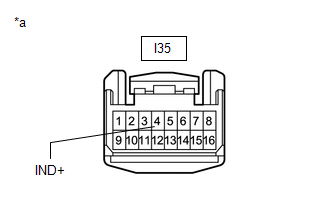
| I35-4 (IND+) - Body ground | Always | 11 to 14 V |
| NG | | REPAIR OR REPLACE HARNESS OR CONNECTOR |
|
| 7. | CHECK HARNESS AND CONNECTOR (AUXILIARY BATTERY - PARKING BRAKE ECU ASSEMBLY) |
(a) Turn the power switch off.
| (b) Disconnect the parking brake ECU assembly connector. |
|
(c) Measure the voltage according to the value(s) in the table below.
Standard Voltage:
| Tester Connection | Condition | Specified Condition |
|---|---|---|
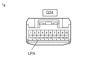
| Q24-13 (LPA) - Body ground | Always | 9 to 14 V |
| OK | | REPLACE PARKING BRAKE ECU ASSEMBLY |
|
| 8. | CHECK HARNESS AND CONNECTOR (PARKING BRAKE ECU ASSEMBLY - ELECTRIC PARKING BRAKE SWITCH (INTEGRATION CONTROL AND PANEL ASSEMBLY)) |
(a) Turn the power switch off.
(b) Disconnect the Q24 parking brake ECU assembly connector.
(c) Disconnect the I35 electric parking brake switch (integration control and panel assembly) connector.
(d) Measure the resistance according to the value(s) in the table below.
Standard Resistance:
| Tester Connection | Condition | Specified Condition |
|---|---|---|
| Q24-13 (LPA) - I35-6 (IND-) | Always | Below 5 Ω |
| Q24-13 (LPA) or I35-6 (IND-) - Body ground | Always | 100 kΩ or higher |
| OK | | REPLACE INTEGRATION CONTROL AND PANEL ASSEMBLY |
| NG | | REPAIR OR REPLACE HARNESS OR CONNECTOR |
READ NEXT:
 Forced Release
Operation MethodOPERATION METHOD PROCEDURE 1. PARKING BRAKE FORCED RELEASE NOTICE: Follow the procedures when using SST to release the parking brake. If the parking brake cannot be released, follow t
Parking Brake System
PrecautionPRECAUTION CAUTION: Perform each part replacement carefully, as mistakes could affect the brake system performance and lead to driving problems. When replacing a part, replace with the same
SEE MORE:
Driving assist systems
To keep driving safety and performance,
the following systems operate
automatically in response to
various driving situations. Be aware,
however, that these systems are
supplementary and should not be
relied upon too heavily when operating
the vehicle.
Summary of the driving assist
systems
Installation
INSTALLATION CAUTION / NOTICE / HINT HINT:
Use the same procedure for the RH and LH sides.
The procedure listed below is for the LH side.
PROCEDURE 1. INSTALL SIDE TELEVISION CAMERA ASSEMBLY LH (a) Install the side television camera assembly LH with the 2 screws. 2. INSTALL LOWER OUTER MIRRO
