Lexus NX: Footwell Light Circuit
DESCRIPTION
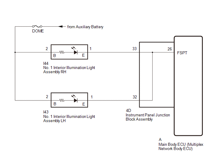
The main body ECU (multiplex network body ECU) controls the operation of the following lights:
- No. 1 interior illumination light assembly LH
- No. 1 interior illumination light assembly RH
WIRING DIAGRAM
CAUTION / NOTICE / HINT
NOTICE:
- Inspect the fuses for circuits related to this system before performing the following procedure.
- Before replacing the main body ECU (multiplex network body ECU), refer to Registration.
PROCEDURE
| 1. | PERFORM ACTIVE TEST USING TECHSTREAM |
(a) Using the Techstream, perform the Active Test.
Click here .gif)
| Tester Display | Measurement Item | Control Range | Diagnostic Note |
|---|---|---|---|
| Fr Foot Light | Turns on the front interior foot lights | ON or OFF | Check the operation with the vehicle stopped, all doors locked and the engine switch off. |
| Tester Display |
|---|
| Fr Foot Light |
OK:
Front interior foot lights illuminate.
| OK | .gif) | PROCEED TO NEXT SUSPECTED AREA SHOWN IN PROBLEM SYMPTOMS TABLE |
|
.gif)
| 2. | CHECK INSTRUMENT PANEL JUNCTION BLOCK ASSEMBLY |
(a) Remove the instrument panel junction block assembly.
Click here
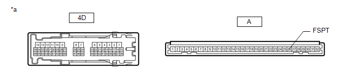
| *a | Component without harness connected (Instrument Panel Junction Block Assembly) | - | - |
(b) Remove the main body ECU (multiplex network body ECU) from the instrument panel junction block assembly.
Click here
(c) Measure the resistance according to the value(s) in the table below.
Standard Resistance:
| Tester Connection | Condition | Specified Condition |
|---|---|---|
| 4D-33 - A-26 (FSPT) | Always | Below 1 Ω |
| OK | | REPLACE MAIN BODY ECU (MULTIPLEX NETWORK BODY ECU) |
| NG | | REPLACE INSTRUMENT PANEL JUNCTION BLOCK ASSEMBLY |
READ NEXT:
 Power Switch Illumination Circuit
DESCRIPTION The illuminated entry system controls the power switch illumination. WIRING DIAGRAM CAUTION / NOTICE / HINT NOTICE:
Recognition code registration is necessary when replacing the main b
Door Unlock Detection Switch Circuit
DESCRIPTION The main body ECU (multiplex network body ECU) detects the condition of each door unlock detection switch. WIRING DIAGRAM CAUTION / NOTICE / HINT NOTICE:
Recognition code registration
Luggage Compartment Room Light
ComponentsCOMPONENTS ILLUSTRATION *1 NO. 1 LUGGAGE COMPARTMENT LIGHT ASSEMBLY - - RemovalREMOVAL PROCEDURE 1. REMOVE NO. 1 LUGGAGE COMPARTMENT LIGHT ASSEMBLY (for LH Side) (a) Put prote
SEE MORE:
Switch Lights of Remote Touch do not Illuminate
DESCRIPTION Power is supplied to the remote touch illumination when the light control switch is in the tail or head position. WIRING DIAGRAM CAUTION / NOTICE / HINT NOTICE: Inspect the fuse for circuits related to this system before performing the following procedure. PROCEDURE 1. CONFIRM SYM
Rough Idling (P1605)
DESCRIPTION When the engine is idling stably under a low load, if the idle speed drops or becomes unstable, this DTC will be stored. Read freeze frame data using the Techstream. The ECM records vehicle and driving condition information as freeze frame data the moment a DTC is stored. When troublesho
