Lexus NX: Front Door Courtesy Switch
Components
COMPONENTS
ILLUSTRATION
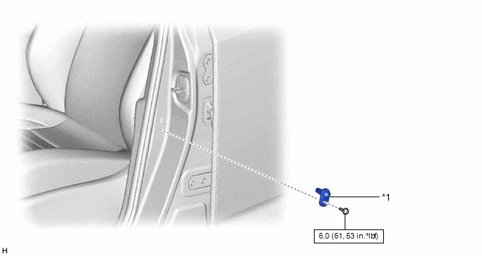
| *1 | FRONT DOOR COURTESY LIGHT SWITCH ASSEMBLY | - | - |
.png) | N*m (kgf*cm, ft.*lbf): Specified torque | - | - |
Removal
REMOVAL
CAUTION / NOTICE / HINT
HINT:
- Use the same procedure for the RH and LH sides.
- The procedure listed below is for the LH side.
PROCEDURE
1. REMOVE FRONT DOOR COURTESY LIGHT SWITCH ASSEMBLY
| (a) Using a T30 "TORX" socket wrench, remove the screw. |
|
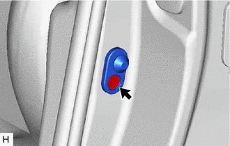
(b) Disconnect the connector and remove the front door courtesy light switch assembly.
Inspection
INSPECTION
CAUTION / NOTICE / HINT
HINT:
- Use the same procedure for the RH and LH sides.
- The procedure listed below is for the LH side.
PROCEDURE
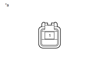
1. INSPECT FRONT DOOR COURTESY LIGHT SWITCH ASSEMBLY
| (a) Measure the resistance according to the value(s) in the table below. Standard Resistance:
If the result is not as specified, replace the front door courtesy light switch assembly. |
|
Installation
INSTALLATION
CAUTION / NOTICE / HINT
HINT:
- Use the same procedure for the RH and LH sides.
- The procedure listed below is for the LH side.
PROCEDURE
1. INSTALL FRONT DOOR COURTESY LIGHT SWITCH ASSEMBLY
(a) Connect the connector.
(b) Using a T30 "TORX" socket wrench, install the front door courtesy light switch assembly with the screw.
Torque:
6.0 N·m {61 kgf·cm, 53 in·lbf}
READ NEXT:
 Components
COMPONENTS ILLUSTRATION *1 DECK FLOOR BOX LH *2 NO. 3 DECK BOARD SUB-ASSEMBLY *3 REAR DECK FLOOR BOX *4 NEGATIVE AUXILIARY BATTERY TERMINAL N*m (kgf*cm, ft.*lbf): Specified
Removal
REMOVAL PROCEDURE 1. DISABLE AUTOAWAY/RETURN FUNCTION (for Power Tilt and Power Telescopic Steering Column) (a) Disable the autoaway/return function by changing the customize parameter. Click here C
SEE MORE:
Installation
INSTALLATION PROCEDURE 1. INSTALL AIR CONDITIONING THERMISTOR ASSEMBLY (HUMIDITY SENSOR) *1 Stopper *2 Bracket (a) Attach the 2 brackets, and carefully install the air conditioning thermistor assembly (humidity sensor) to the glass surface, preventing air bubbles from forming between
Utility
UTILITY NOTICE: If any of the following parts has been replaced due to pre-collision system malfunction, those systems using those parts may be affected without performing necessary operations.
Forward recognition camera HINT: Forward recognition camera adjustment can be performed by using either
