Lexus NX: Fuel Injector Circuit
DESCRIPTION
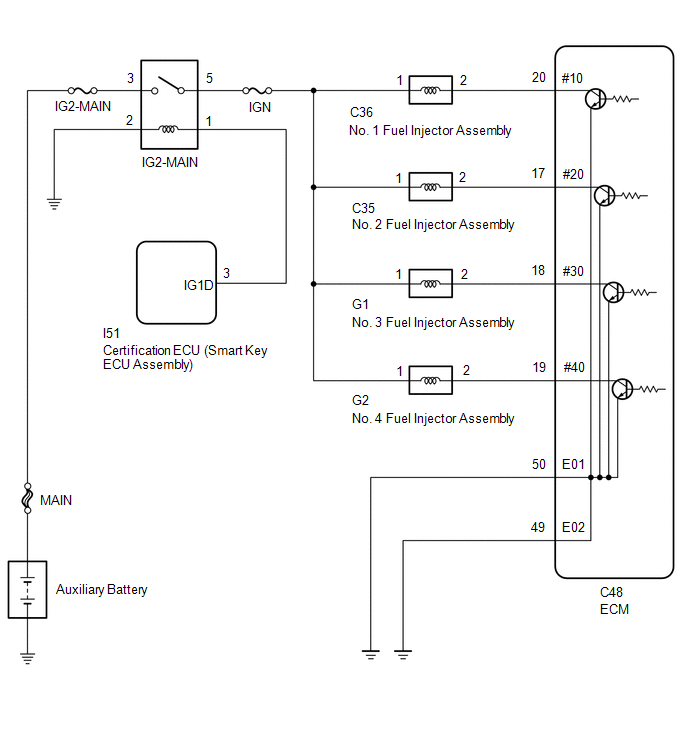
The fuel injector assemblies are located on the intake port. They inject fuel into the cylinders based on the signals from the ECM.
WIRING DIAGRAM
CAUTION / NOTICE / HINT
NOTICE:
Inspect the fuses for circuits related to this system before performing the following procedure.
PROCEDURE
| 1. | CHECK TERMINAL VOLTAGE (POWER SOURCE OF FUEL INJECTOR ASSEMBLY) |
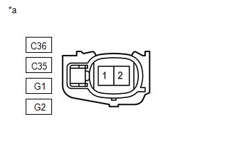
| *a | Front view of wire harness connector (to Fuel Injector Assembly) |
(a) Disconnect the fuel injector assembly connector.
(b) Turn the power switch on (IG).
(c) Measure the voltage according to the value(s) in the table below.
Standard Voltage:
| Tester Connection | Condition | Specified Condition |
|---|---|---|
| C36-1 - Body ground | Power switch on (IG) | 11 to 14 V |
| C35-1 - Body ground | Power switch on (IG) | 11 to 14 V |
| G1-1 - Body ground | Power switch on (IG) | 11 to 14 V |
| G2-1 - Body ground | Power switch on (IG) | 11 to 14 V |
| NG | .gif) | GO TO STEP 4 |
|
.gif)
| 2. | INSPECT FUEL INJECTOR ASSEMBLY |
(a) Inspect the fuel injector assembly.
Click here .gif)
HINT:
Perform "Inspection After Repair" after replacing the fuel injector assembly.
Click here
| NG | | REPLACE FUEL INJECTOR ASSEMBLY |
|
| 3. | CHECK HARNESS AND CONNECTOR (FUEL INJECTOR ASSEMBLY - ECM) |
(a) Disconnect the fuel injector assembly connector.
(b) Disconnect the ECM connector.
(c) Measure the resistance according to the value(s) in the table below.
Standard Resistance:
| Tester Connection | Condition | Specified Condition |
|---|---|---|
| C36-2 - C48-20 (#10) | Always | Below 1 Ω |
| C35-2 - C48-17 (#20) | Always | Below 1 Ω |
| G1-2 - C48-18 (#30) | Always | Below 1 Ω |
| G2-2 - C48-19 (#40) | Always | Below 1 Ω |
| C36-2 or C48-20 (#10) - Body ground | Always | 10 kΩ or higher |
| C35-2 or C48-17 (#20) - Body ground | Always | 10 kΩ or higher |
| G1-2 or C48-18 (#30) - Body ground | Always | 10 kΩ or higher |
| G2-2 or C48-19 (#40) - Body ground | Always | 10 kΩ or higher |
| OK | | PROCEED TO NEXT SUSPECTED AREA SHOWN IN PROBLEM SYMPTOMS TABLE |
| NG | | REPAIR OR REPLACE HARNESS OR CONNECTOR |
| 4. | CHECK HARNESS AND CONNECTOR (IG2-MAIN RELAY - FUEL INJECTOR ASSEMBLY) |
(a) Remove the IG2-MAIN relay from the No. 1 engine room relay block and junction block assembly.
(b) Disconnect the fuel injector assembly connector.
(c) Measure the resistance according to the value(s) in the table below.
Standard Resistance:
| Tester Connection | Condition | Specified Condition |
|---|---|---|
| 5 (IG2-MAIN relay) - C36-1 | Always | Below 1 Ω |
| 5 (IG2-MAIN relay) - C35-1 | Always | Below 1 Ω |
| 5 (IG2-MAIN relay) - G1-1 | Always | Below 1 Ω |
| 5 (IG2-MAIN relay) - G2-1 | Always | Below 1 Ω |
| 5 (IG2-MAIN relay) or C36-1 - Body ground | Always | 10 kΩ or higher |
| 5 (IG2-MAIN relay) or C35-1 - Body ground | Always | 10 kΩ or higher |
| 5 (IG2-MAIN relay) or G1-1 - Body ground | Always | 10 kΩ or higher |
| 5 (IG2-MAIN relay) or G2-1 - Body ground | Always | 10 kΩ or higher |
| OK | | GO TO ECM POWER SOURCE CIRCUIT |
| NG | | REPAIR OR REPLACE HARNESS OR CONNECTOR |
READ NEXT:
 MIL Circuit
DESCRIPTION The Malfunction Indicator Lamp (MIL) is used to indicate vehicle malfunctions detected by the ECM. The MIL operation can be checked visually. When the power switch is turned on (IG), the M
Rough Idling
DESCRIPTION Problem Symptom Suspected Area Trouble Area
Engine speed fluctuation due to abnormal combustion
Idle speed too low or high
Strong engine vibration due to above symptoms
SEE MORE:
Precaution
PRECAUTION NOTICE: When disassembling the headlight assembly, use static electricity countermeasures SST (desktop antistatic mat set) and observe all precautions to prevent damage to the system by electrostatic discharge (ESD). STATIC ELECTRICITY COUNTERMEASURES SST SST:Desktop antistatic mat set (0
Precaution
PRECAUTION CAUTION REGARDING INTERFERENCE WITH ELECTRONIC DEVICES CAUTION:
People with implantable cardiac pacemakers, cardiac resynchronization therapy-pacemakers or implantable cardioverter defibrillators should keep away from the smart access system antennas. The radio waves may affect the ope
