Lexus NX: GVIF Disconnected (from EMV/MM Integrated Device to Multi Display) (B1575)
DESCRIPTION
| DTC No. | Detection Item | DTC Detection Condition | Trouble Area |
|---|---|---|---|
| B1575 | GVIF Disconnected (from EMV/MM Integrated Device to Multi Display) | GVIF disconnected (from radio receiver assembly to multi-display assembly) |
|
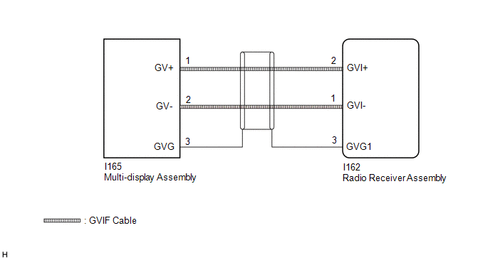
WIRING DIAGRAM
CAUTION / NOTICE / HINT
NOTICE:
When replacing the radio receiver assembly, always replace it with a new one.
If a radio receiver assembly which was installed to another vehicle is used, the following may occur:
- A communication malfunction DTC may be stored.
- The radio receiver assembly may not operate normally.
HINT:
Depending on the parts that are replaced during vehicle inspection or maintenance, performing initialization, registration or calibration may be needed. Refer to Precaution for Audio and Visual System.
Click here .gif)
PROCEDURE
| 1. | CHECK DTC |
(a) Clear the DTCs.
Click here
(b) Turn the power switch off.
(c) Recheck for DTCs and check that no DTCs are output.
Click here
OK:
No DTCs are output.
| OK | .gif) | USE SIMULATION METHOD TO CHECK |
|
.gif)
| 2. | CHECK HARNESS AND CONNECTOR (MULTI-DISPLAY - RADIO RECEIVER ASSEMBLY) |
| (a) Disconnect the I165 multi-display assembly connector. |
|
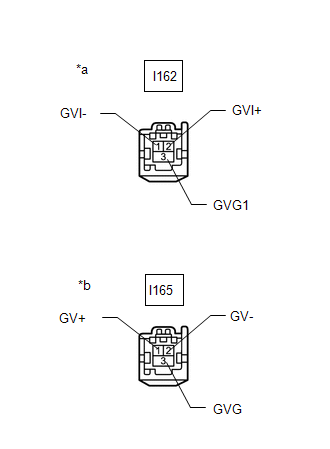
(b) Disconnect the I162 radio receiver assembly connector.
(c) Measure the resistance according to the value(s) in the table below.
Standard Resistance:
| Tester Connection | Condition | Specified Condition |
|---|---|---|
| I162-2 (GVI+) - I165-1 (GV+) | Always | Below 1 Ω |
| I162-1 (GVI-) - I165-2 (GV-) | Always | Below 1 Ω |
| I162-3 (GVG1) - I165-3 (GVG) | Always | Below 1 Ω |
| I162-2 (GVI+) - Body ground | Always | 10 kΩ or higher |
| I162-1 (GVI-) - Body ground | Always | 10 kΩ or higher |
| I162-3 (GVG1) - Body ground | Always | 10 kΩ or higher |
| NG | | REPAIR OR REPLACE HARNESS OR CONNECTOR |
|
| 3. | CHECK MULTI-DISPLAY ASSEMBLY |
(a) Replace the multi-display assembly with a new or known good one.
Click here
(b) Clear the DTCs.
Click here
(c) Turn the power switch off.
(d) Recheck for DTCs and check that no DTCs are output.
Click here
OK:
No DTCs are output.
| OK | | END (MULTI-DISPLAY ASSEMBLY IS DEFECTIVE) |
| NG | | REPLACE RADIO RECEIVER ASSEMBLY |
READ NEXT:
 Voice Recognition Microphone Disconnected (B1579)
DESCRIPTION The radio receiver assembly and telephone microphone assembly are connected to each other using the microphone connection detection signal lines. This DTC is stored when a microphone conne
USB Device Malfunction (B1585)
DESCRIPTION This DTC is stored when a malfunction occurs in a connected device. DTC No. Detection Item DTC Detection Condition Trouble Area B1585 USB Device Malfunction When one of th
AV Signal Stoppage (Low Battery Voltage) (B158F)
DESCRIPTION This DTC is stored when a video or audio signal is interrupted due to auxiliary battery voltage input to the radio receiver assembly dropping temporarily. DTC No. Detection Item DTC
SEE MORE:
Brake Control Warning Light does not Come ON
DESCRIPTION The skid control ECU (brake booster with master cylinder assembly) is connected to the combination meter assembly via CAN communication. CAUTION / NOTICE / HINT NOTICE: When replacing the skid control ECU (brake booster with master cylinder assembly), perform initialization and calibrati
Ambient Temperature Display System
DESCRIPTION The thermistor assembly (ambient temperature sensor) is installed in front of the cooler condenser assembly to detect the ambient temperature which is used to control the air conditioning system AUTO mode. This sensor is connected to the air conditioning amplifier assembly and detects fl
