Lexus NX: GVIF Disconnected (from Park Assist/Monitoring ECU to EMV/MM Integrated Device) (B1574)
DESCRIPTION
| DTC No. | Detection Item | DTC Detection Condition | Trouble Area |
|---|---|---|---|
| B1574 | GVIF Disconnected (from Park Assist/Monitoring ECU to EMV/MM Integrated Device) | GVIF disconnected (from parking assist ECU to multi-display assembly) |
|
WIRING DIAGRAM

CAUTION / NOTICE / HINT
HINT:
Depending on the parts that are replaced during vehicle inspection or maintenance, performing initialization, registration or calibration may be needed. Refer to Precaution for Navigation System.
Click here .gif)
PROCEDURE
| 1. | CHECK DTC |
(a) Clear the DTCs.
Click here
(b) Turn the power switch off.
(c) Recheck for DTCs and check that no DTCs are output.
Click here
OK:
No DTCs are output.
| OK | .gif) | USE SIMULATION METHOD TO CHECK |
|
.gif)
| 2. | CHECK HARNESS AND CONNECTOR (MULTI-DISPLAY ASSEMBLY - PARKING ASSIST ECU) |
| (a) Disconnect the I177 multi-display assembly connector. |
|
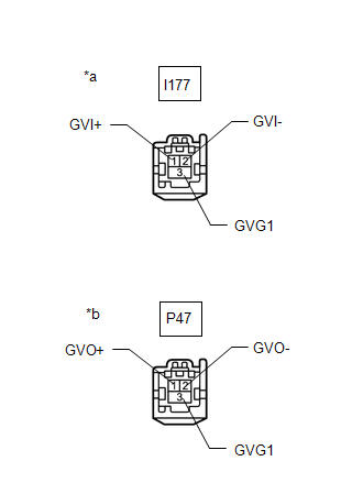
(b) Disconnect the P47 radio receiver assembly connector.
(c) Measure the resistance according to the value(s) in the table below.
Standard Resistance:
| Tester Connection | Condition | Specified Condition |
|---|---|---|
| P47-1 (GVO+) - I177-1 (GVI+) | Always | Below 1 Ω |
| P47-2 (GVO-) - I177-2 (GVI-) | Always | Below 1 Ω |
| P47-3 (GVG1) - I177-3 (GVG1) | Always | Below 1 Ω |
| P47-1 (GVO+) - Body ground | Always | 10 kΩ or higher |
| P47-2 (GVO-) - Body ground | Always | 10 kΩ or higher |
| P47-3 (GVG1) - Body ground | Always | 10 kΩ or higher |
| NG | | REPAIR OR REPLACE HARNESS OR CONNECTOR |
|
| 3. | CHECK MULTI-DISPLAY ASSEMBLY |
(a) Replace the multi-display assembly with a new or known good one.
Click here
(b) Clear the DTCs.
Click here
(c) Turn the power switch off.
(d) Recheck for DTCs and check that no DTCs are output.
Click here
OK:
No DTCs are output.
| OK | | END (MULTI-DISPLAY ASSEMBLY IS DEFECTIVE) |
| NG | | REPLACE PARKING ASSIST ECU |
READ NEXT:
 GVIF Disconnected (from EMV/MM Integrated Device to Multi Display) (B1575)
DESCRIPTION DTC No. Detection Item DTC Detection Condition Trouble Area B1575 GVIF Disconnected (from EMV/MM Integrated Device to Multi Display) GVIF disconnected (from radio receiver
Voice Recognition Microphone Disconnected (B1579)
DESCRIPTION The radio receiver assembly and telephone microphone assembly are connected to each other using the microphone connection detection signal lines. This DTC is stored when a microphone conne
USB Device Malfunction (B1585)
DESCRIPTION This DTC is stored when a malfunction occurs in a connected device. DTC No. Detection Item DTC Detection Condition Trouble Area B1585 USB Device Malfunction When one of th
SEE MORE:
Components
COMPONENTS ILLUSTRATION *1 AIR CLEANER CAP SUB-ASSEMBLY *2 AIR CLEANER CASE SUB-ASSEMBLY *3 AIR CLEANER FILTER ELEMENT SUB-ASSEMBLY *4 HEATER ACCESSORY ASSEMBLY *5 HEATER WATER INLET HOSE A *6 HEATER WATER OUTLET HOSE A *7 FUEL VAPOR FEED HOSE *8 NO. 2 FUEL VA
Electrical Key Oscillator(for Rear Floor)
ComponentsCOMPONENTS ILLUSTRATION *1 NO. 2 CONSOLE BOX MOUNTING BRACKET *2 NO. 2 INDOOR ELECTRICAL KEY ANTENNA ASSEMBLY N*m (kgf*cm, ft.*lbf): Specified torque - - RemovalREMOVAL PROCEDURE 1. REMOVE REAR CONSOLE BOX ASSEMBLY Click here 2. REMOVE NO. 2 CONSOLE BOX MOUNTIN
