Lexus NX: Hazard Warning Switch Circuit
DESCRIPTION
When the combination meter receives a hazard warning signal switch signal, the flasher IC turns on and hazard control is performed.
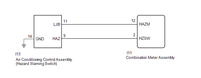
WIRING DIAGRAM
CAUTION / NOTICE / HINT
NOTICE:
When replacing the combination meter assembly, make sure to replace it with a new one.
PROCEDURE
| 1. | READ VALUE USING TECHSTREAM (HAZARD FLASHER SWITCH) |
(a) Using the Techstream, read the Data List.
Click here .gif)
| Tester Display | Measurement Item | Range | Normal Condition | Diagnostic Note |
|---|---|---|---|---|
| Hazard Flasher Switch | Hazard warning signal switch signal | ON or OFF | ON: Hazard switch on OFF: Hazard switch off | - |
| Tester Display |
|---|
| Hazard Flasher Switch |
| OK | .gif) | PROCEED TO NEXT SUSPECTED AREA SHOWN IN PROBLEM SYMPTOMS TABLE |
|
.gif)
| 2. | INSPECT AIR CONDITIONING CONTROL ASSEMBLY (HAZARD WARNING SWITCH) |
(a) Remove the air conditioning control assembly (hazard warning switch).
Click here
(b) Inspect the air conditioning control assembly (hazard warning switch).
Click here
| NG | | REPLACE AIR CONDITIONING CONTROL ASSEMBLY (HAZARD WARNING SIGNAL SWITCH) |
|
| 3. | CHECK HARNESS AND CONNECTOR (AIR CONDITIONING CONTROL ASSEMBLY [HAZARD WARNING SWITCH] - COMBINATION METER ASSEMBLY) |
(a) Disconnect the I13 air conditioning control assembly (hazard warning switch) connector.
(b) Disconnect the I11 combination meter assembly connector.
(c) Measure the resistance according to the value(s) in the table below.
Standard Resistance:
| Tester Connection | Condition | Specified Condition |
|---|---|---|
| I13-9 (HAZ) - I11-2 (HZSW) | Always | Below 1 Ω |
| I13-11 (LJB) - I11-12 (HAZM) | Always | Below 1 Ω |
| I13-14 (GND) - Body ground | Always | Below 1 Ω |
| I13-9 (HAZ) or I11-2 (HZSW) - Body ground | Always | 10 kΩ or higher |
| I13-11 (LJB) or I11-12 (HAZM) - Body ground | Always | 10 kΩ or higher |
| OK | | REPLACE COMBINATION METER ASSEMBLY |
| NG | | REPAIR OR REPLACE HARNESS OR CONNECTOR |
READ NEXT:
 Taillight Relay Circuit
DESCRIPTION Illumination of the taillights and license plate light is controlled by the main body ECU (multiplex network body ECU). WIRING DIAGRAM CAUTION / NOTICE / HINT NOTICE:
Inspect the fuse
Low Beam Headlight Circuit
DESCRIPTION The main body ECU (multiplex network body ECU) controls the low beam headlights. WIRING DIAGRAM CAUTION / NOTICE / HINT NOTICE:
Inspect the fuses for circuits related to this system be
High Beam Headlight Circuit
DESCRIPTION The main body ECU (multiplex network body ECU) controls the high beam headlights. WIRING DIAGRAM CAUTION / NOTICE / HINT NOTICE:
Inspect the fuses for circuits related to this system b
SEE MORE:
Front Left Seat Heat Sensor Circuit (B14C1)
DESCRIPTION Output to the front seat cushion heater temperature sensor stops if one of the following occurs: 1) the temperature sensor is open or shorted; or 2) the temperature sensor is damaged and its output value does not change. DTC No. Detection Item DTC Detection Condition Trouble Are
High Voltage Power Resource (P3004-131)
DTC SUMMARY MALFUNCTION DESCRIPTION The hybrid vehicle control ECU monitors the high-voltage wiring between the HV battery and inverter with converter assembly and detects an open circuit malfunction. The cause of this malfunction may be one of the following: Inside of inverter voltage sensor (VH)
