Lexus NX: Headlight Swivel Motor LH (B2412,B2413)
DESCRIPTION
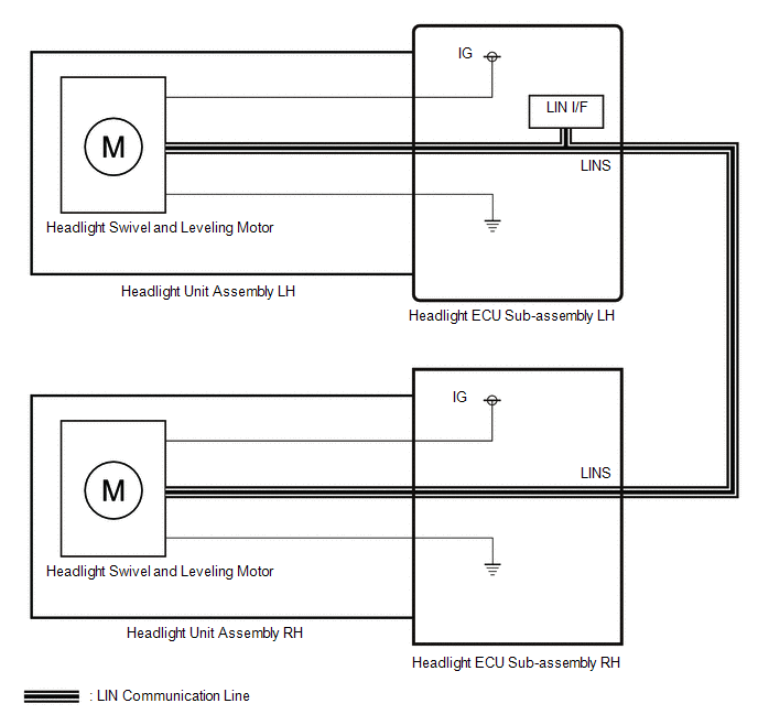
The headlight ECU sub-assembly LH sends automatic headlight beam level control signals to each headlight swivel and leveling motor via LIN communication.
Each headlight ECU sub-assembly and headlight swivel and leveling motor communicate via LIN communication.
The headlight swivel and leveling motor operates according to power supplied and automatic headlight beam level control signals from its respective headlight ECU sub-assembly and sends its operating state to the headlight ECU sub-assembly.
The headlight ECU sub-assembly LH stores a DTC if it detects that a headlight swivel and leveling motor is malfunctioning.
| DTC No. | Detection Item | DTC Detection Condition | Trouble Area |
|---|---|---|---|
| B2412 | Headlight Swivel Motor LH |
| Headlight unit assembly LH |
| B2413 | Headlight Swivel Motor RH |
| Headlight unit assembly RH |
WIRING DIAGRAM
CAUTION / NOTICE / HINT
NOTICE:
If the headlight ECU sub-assembly LH has been replaced, it is necessary to synchronize the vehicle information and initialize the headlight ECU sub-assembly LH.
Click here .gif)
PROCEDURE
| 1. | CHECK FOR DTC |
(a) Clear the DTCs.
Click here
(b) Turn the power switch on (IG).
(c) Check for DTCs.
Click here
OK:
DTC B2412 and B2413 are not outputs.
| Result | Proceed to |
|---|---|
| OK | A |
| NG (DTC B2412 is output) | B |
| NG (DTC B2413 is output) | C |
| A | .gif) | USE SIMULATION METHOD TO CHECK |
| B | | REPLACE HEADLIGHT UNIT ASSEMBLY LH |
| C | | REPLACE HEADLIGHT UNIT ASSEMBLY RH |
READ NEXT:
 Parts Location
PARTS LOCATION ILLUSTRATION *1 REAR HEIGHT CONTROL SENSOR SUB-ASSEMBLY LH *2 BRAKE BOOSTER WITH MASTER CYLINDER ASSEMBLY (SKID CONTROL ECU) *3 HEADLIGHT ASSEMBLY LH - HEADLIGHT ECU SUB
System Diagram
SYSTEM DIAGRAM
SEE MORE:
Television Camera (for Front)
ComponentsCOMPONENTS ILLUSTRATION *1 FRONT TELEVISION CAMERA ASSEMBLY - - RemovalREMOVAL PROCEDURE 1. PRECAUTION Click here 2. REMOVE FRONT BUMPER COVER (a) for Sport Package: Click here (b) except Sport Package: Click here 3. REMOVE FRONT TELEVISION CAMERA ASSEMBLY (a) Disco
Removal
REMOVAL CAUTION / NOTICE / HINT HINT:
Use the same procedure for the RH and LH sides.
The procedure listed below is for the LH side.
PROCEDURE 1. REMOVE OUTER MIRROR LH (a) Push the upper part of the mirror surface and tilt it. (b) Apply protective tape to the areas shown in the illustrat
