Lexus NX: Horn
Components
COMPONENTS
ILLUSTRATION
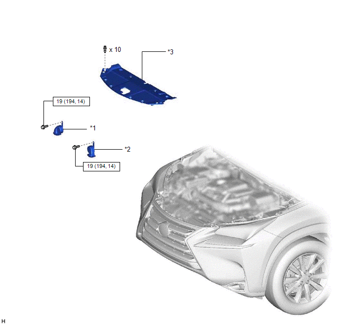
| *1 | HIGH PITCHED HORN ASSEMBLY | *2 | LOW PITCHED HORN ASSEMBLY |
| *3 | RADIATOR SUPPORT OPENING COVER | - | - |
.png) | N*m (kgf*cm, ft.*lbf): Specified torque | - | - |
Removal
REMOVAL
PROCEDURE
1. REMOVE RADIATOR SUPPORT OPENING COVER
Click here .gif)
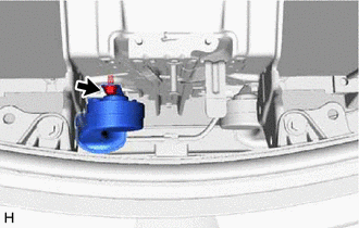
2. REMOVE HIGH PITCHED HORN ASSEMBLY
(a) Disconnect the connector.
| (b) Remove the bolt and high pitched horn assembly. |
|
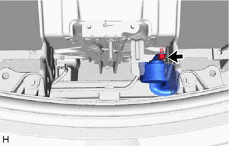
3. REMOVE LOW PITCHED HORN ASSEMBLY
(a) Disconnect the connector.
| (b) Remove the bolt and low pitched horn assembly. |
|
Inspection
INSPECTION
PROCEDURE
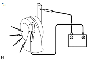
1. INSPECT HIGH PITCHED HORN ASSEMBLY
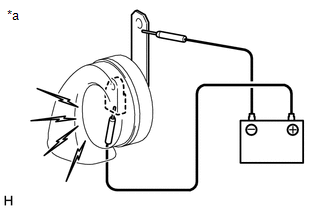
| *a | Component without harness connected (High Pitched Horn Assembly) |
(a) Apply battery voltage and check operation of the high pitched horn according to the table below.
OK:
| Measurement Condition | Specified Condition |
|---|---|
| Battery positive (+) → Terminal 1 Battery negative (-) → Horn body | High pitched horn sounds |
If the result is not as specified, replace the high pitched horn assembly.
2. INSPECT LOW PITCHED HORN ASSEMBLY
| *a | Component without harness connected (Low Pitched Horn Assembly) |
(a) Apply battery voltage and check operation of the low pitched horn according to the table below.
OK:
| Measurement Condition | Specified Condition |
|---|---|
| Battery positive (+) → Terminal 1 Battery negative (-) → Horn body | Low pitched horn sounds |
If the result is not as specified, replace the low pitched horn assembly.
READ NEXT:
 Horn System
Parts LocationPARTS LOCATION ILLUSTRATION *1 LOW PITCHED HORN ASSEMBLY *2 HIGH PITCHED HORN ASSEMBLY *3 HORN RELAY *4 SPIRAL CABLE SUB-ASSEMBLY *5 STEERING PAD SWITCH ASSEMB
Relay
On-vehicle InspectionON-VEHICLE INSPECTION PROCEDURE 1. INSPECT HORN RELAY ASSEMBLY (a) Remove the horn relay assembly. (b) Measure the resistance according to the value(s) in the tabl
SEE MORE:
Indicator Circuit
DESCRIPTION The LTA/LDA indicator output request signal is sent from the forward recognition camera to the combination meter assembly via CAN communication. CAUTION / NOTICE / HINT NOTICE:
When replacing the forward recognition camera, make sure to replace it with a new one. If a device that was
ECU Power Source Circuit
DESCRIPTION If the power switch is on (IG), the hybrid vehicle control ECU applies current to the MREL terminal to turn the IGCT relay on. This supplies power to the +B1 and +B2 terminals. WIRING DIAGRAM Refer to the wiring diagram for DTC P0A08-264. Click here PROCEDURE 1. CHECK HYBRID VE
