Lexus NX: Hybrid Vehicle Control Ecu
Components
COMPONENTS
ILLUSTRATION
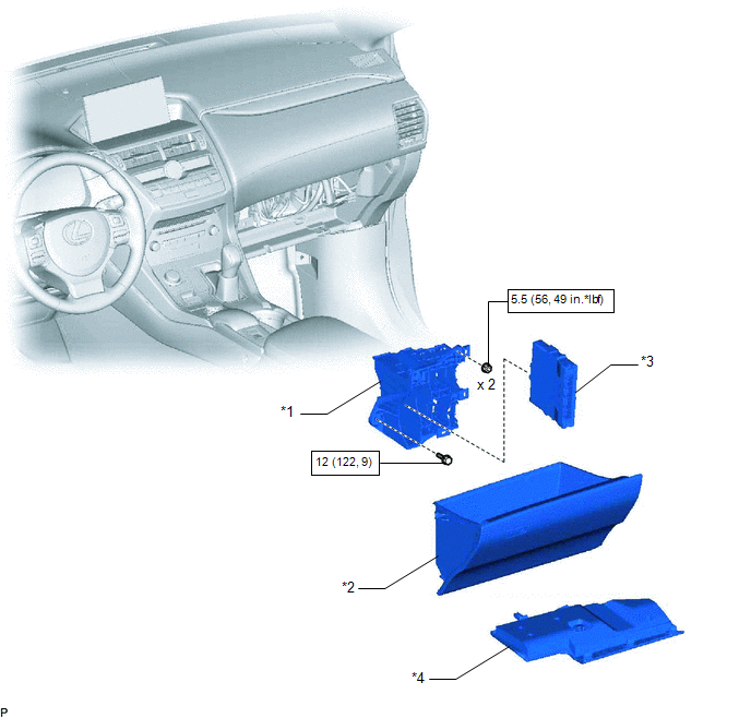
| *1 | ECU INTEGRATION BOX RH | *2 | GLOVE COMPARTMENT DOOR ASSEMBLY |
| *3 | HYBRID VEHICLE CONTROL ECU | *4 | NO. 2 INSTRUMENT PANEL UNDER COVER SUB-ASSEMBLY |
.png) | N*m (kgf*cm, ft.*lbf): Specified torque | - | - |
Removal
REMOVAL
PROCEDURE
1. PRECAUTION
NOTICE:
After turning the power switch is turned off, there may be a waiting time before disconnecting the auxiliary negative (-) battery terminal.
Click here .gif)
2. DISCONNECT CABLE FROM NEGATIVE AUXILIARY BATTERY TERMINAL
3. REMOVE NO. 2 INSTRUMENT PANEL UNDER COVER SUB-ASSEMBLY
Click here
4. REMOVE GLOVE COMPARTMENT DOOR ASSEMBLY
Click here
5. REMOVE ECU INTEGRATION BOX RH
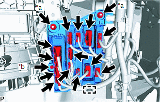
| *a | Nut |
| *b | Bolt |
(a) Disconnect the 13 connectors and clamp.
(b) Remove the 2 nuts, bolt and ECU integration box RH.
6. REMOVE HYBRID VEHICLE CONTROL ECU
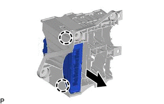
(a) Disconnect the 2 claws and remove the hybrid vehicle control ECU from the ECU integration box RH.
Installation
INSTALLATION
PROCEDURE
1. INSTALL HYBRID VEHICLE CONTROL ECU
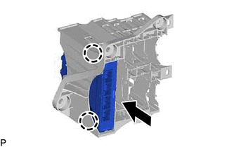
(a) Attach the 2 claws and install the hybrid vehicle control ECU to the ECU integration box RH.
2. INSTALL ECU INTEGRATION BOX RH
(a) Install the ECU integration box RH with the 2 nuts and bolt.
Torque:
for Nut :
5.5 N·m {56 kgf·cm, 49 in·lbf}
for Bolt :
12 N·m {122 kgf·cm, 9 ft·lbf}
(b) Connect the 13 connectors and clamp.
3. INSTALL GLOVE COMPARTMENT DOOR ASSEMBLY
Click here .gif)
4. INSTALL NO. 2 INSTRUMENT PANEL UNDER COVER SUB-ASSEMBLY
Click here
5. CONNECT CABLE TO NEGATIVE AUXILIARY BATTERY TERMINAL
6. INITIALIZATION AFTER RECONECTING AUXILIARY BATTERY TERMINAL
Click here
HINT:
When disconnecting and reconnecting the auxiliary battery, there is an automatic learning function that completes learning when the respective system is used.
Click here
READ NEXT:
 Components
COMPONENTS ILLUSTRATION *1 DECK FLOOR BOX LH *2 NO. 3 DECK BOARD SUB-ASSEMBLY *3 REAR DECK FLOOR BOX *4 NEGATIVE AUXILIARY BATTERY TERMINAL N*m (kgf*cm, ft.*lbf): Specified
Removal
REMOVAL PROCEDURE 1. PRECAUTION Click here 2. REMOVE SERVICE PLUG GRIP Click here 3. DRAIN COOLANT (for Inverter Coolant) Click here 4. DISCONNECT WIRE HARNESS (a) Disconnect the 4 wire harn
SEE MORE:
Switch Lights of Remote Touch do not Illuminate
DESCRIPTION Power is supplied to the remote touch illumination when the light control switch is in the tail or head position. WIRING DIAGRAM CAUTION / NOTICE / HINT NOTICE: Inspect the fuse for circuits related to this system before performing the following procedure. PROCEDURE 1. CONFIRM SYM
Catalyst System Efficiency Below Threshold (Bank 1) (P0420)
MONITOR DESCRIPTION The ECM uses sensors mounted in front of and behind the Three-Way Catalytic Converter (TWC) to monitor its efficiency. The first sensor, the air fuel ratio sensor, sends pre-catalyst information to the ECM. The second sensor, the heated oxygen sensor, sends post-catalyst informat
