Lexus NX: Inspection
INSPECTION
PROCEDURE
1. INSPECT CHARCOAL CANISTER ASSEMBLY
| (a) Visually check the charcoal canister assembly for cracks or damage. If cracks or damage is found, replace the charcoal canister assembly. |
|
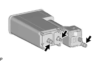
(b) Check the canister operation.
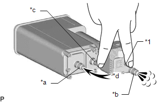
| *1 | Connector |
| *a | Vent Line Port |
| *b | Air Inlet Line Port |
| *c | Purge Line Port |
| *d | Air |
(1) With the purge line port and connector closed, blow air at 5 kPa (0.1 kgf/cm2, 0.7 psi) into the vent line port and check that air flows from the air inlet line port.
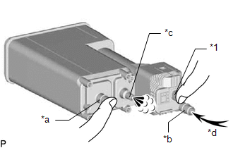
| (2) With the vent line port and connector closed, blow air at 5 kPa (0.1 kgf/cm2, 0.7 psi) into the air inlet line port and check that air flows from the purge line port. If the result is not as specified, replace the charcoal canister assembly. |
|
(c) Check for air leaks.
| (1) Connect a pressure gauge to the vent line port of the charcoal canister assembly. |
|
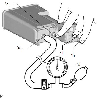
(2) With the purge line port, air inlet line port and connector closed, apply pressurized air at 19.6 kPa (0.2 kgf/cm2, 2.8 psi) into the vent line port, and then confirm that pressure is retained for 1 minute.
If the result is not as specified, replace the charcoal canister assembly.
READ NEXT:
 Installation
INSTALLATION PROCEDURE 1. INSTALL CANISTER PUMP MODULE (a) Engage the 2 claws to install a new canister pump module to the charcoal canister assembly. NOTICE:
Do not allow foreign matter such
Egr Cooler
ComponentsCOMPONENTS ILLUSTRATION *1 EGR COOLER ASSEMBLY *2 NO. 5 WATER BY-PASS HOSE *3 STUD BOLT *4 GASKET *5 NO. 1 WATER BY-PASS PIPE *6 NO. 1 EGR PIPE N*m (kgf
SEE MORE:
Installation
INSTALLATION PROCEDURE 1. INSTALL STOP LIGHT SWITCH ASSEMBLY (a) Turn the stop light switch assembly in the clockwise direction until it reaches the standard shaft protrusion amount and temporarily install it. Standard: 0.5 to 1.7 mm (0.0197 to 0.0669 in.) NOTICE: Do not depress the brake pedal.
Camshaft Position "A" Actuator Circuit (Bank 1) (P0010)
DESCRIPTION The Variable Valve Timing (VVT) system adjusts the intake valve timing to improve driveability. The engine oil pressure turns the VVT controller to adjust the valve timing. The camshaft timing oil control valve assembly is a solenoid valve and switches the engine oil line. The valve move
