Lexus NX: Inspection
INSPECTION
PROCEDURE
1. INSPECT HV BATTERY JUNCTION BLOCK ASSEMBLY
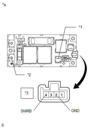
| (a) Inspect SMRB: (1) Measure the resistance according to the value(s) in the table below. Standard Resistance:
(2) Measure the resistance according to the value(s) in the table below. Standard Resistance:
If the result is not as specified, replace the hybrid battery junction block assembly. |
|
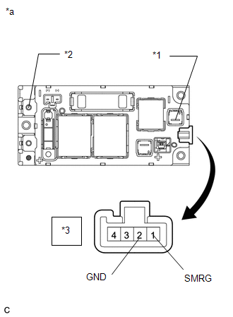
| (b) Inspect SMRG: (1) Measure the resistance according to the value(s) in the table below. Standard Resistance:
(2) Measure the resistance according to the value(s) in the table below. Standard Resistance:
If the result is not as specified, replace the hybrid battery junction block assembly. |
|
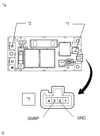
| (c) Inspect SMRP: (1) Measure the resistance according to the value(s) in the table below. Standard Resistance:
(2) Measure the resistance according to the value(s) in the table below. Standard Resistance:
If the result is not as specified, replace the hybrid battery junction block assembly. |
|
READ NEXT:
 Installation
INSTALLATION PROCEDURE 1. INSTALL HV BATTERY JUNCTION BLOCK ASSEMBLY CAUTION: Wear insulated gloves and use insulated tools. (a) Install the hybrid battery junction block assembly with the 3 nuts. Tor
Dtc Check / Clear
DTC CHECK / CLEAR CHECK FOR DTCS (a) Connect the Techstream to the DLC3. (b) Turn the power switch on (IG). (c) Turn the Techstream on. (d) Enter the following menus: Powertrain / Hybrid Control / Tro
SEE MORE:
Installation
INSTALLATION CAUTION / NOTICE / HINT HINT:
Use the same procedure for the RH and LH sides.
The procedure listed below is for the LH side.
PROCEDURE 1. INSTALL SIDE TELEVISION CAMERA ASSEMBLY LH (a) Install the side television camera assembly LH with the 2 screws. 2. INSTALL LOWER OUTER MIRRO
System Description
SYSTEM DESCRIPTION
The theft deterrent system can be set/canceled by locking/unlocking the doors performing any of the following operation:
Entry lock/unlock operation
Wireless lock/unlock operation*1
Key linked lock/unlock operation
By opening and closing the doors*2
*1: Using the re
