Lexus NX: Inspection
INSPECTION
PROCEDURE
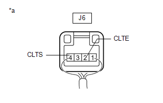
1. INSPECT AUTOMATIC LIGHT CONTROL SENSOR
| (a) Disconnect the automatic light control sensor connector. |
|
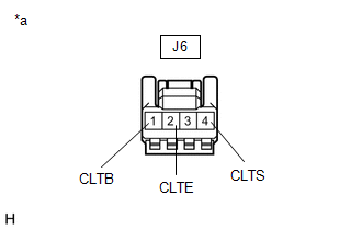
(b) Measure the voltage and resistance according to the value(s) in the table below.
Standard Voltage:
| Tester Connection | Condition | Specified Condition |
|---|---|---|
| J6-1 (CLTB) - J6-2 (CLTE) | Power switch off | Below 1 V |
| Power switch on (IG) | 11 to 14 V |
Standard Resistance:
| Tester Connection | Condition | Specified Condition |
|---|---|---|
| J6-2 (CLTE) - Body ground | Always | Below 1 Ω |
If the result is not as specified, there may be a malfunction on the wire harness side.
| (c) Reconnect the automatic light control sensor connector. |
|
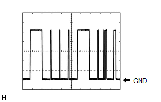
(d) Connect an oscilloscope to the automatic light control sensor connector.
| (e) Check the waveform. OK:
HINT: The communication waveform changes according to the surrounding brightness. If the result is not as specified, the automatic light control sensor may be malfunctioning. |
|
READ NEXT:
 Installation
INSTALLATION PROCEDURE 1. INSTALL AUTOMATIC LIGHT CONTROL SENSOR (a) Attach the 2 claws to install the automatic light control sensor. 2. INSTALL NO. 1 SPEAKER OPENING COVER ASSEMBLY Click here 3.
Components
COMPONENTS ILLUSTRATION *1 CLEARANCE LIGHT ASSEMBLY LH *2 FRONT BUMPER ASSEMBLY *3 FRONT TURN SIGNAL LIGHT BULB - -
SEE MORE:
Lexus Safety System+ 2.0
The Lexus Safety System+ 2.0 consists
of the following drive assist systems
and contributes to a safe and
comfortable driving experience:
Driving assist system
PCS (Pre-Collision System)
LTA (Lane Tracing Assist)
LDA (Lane Departure Alert with
steering control)
Automatic High Beam
Main Microcomputer in Front Radar Sensor Calibration/Parameter Memory Failure (C1A8C46,C1A8D1C,C1A9000,C1A9100)
DESCRIPTION When an internal malfunction is detected in the millimeter wave radar sensor assembly, a DTC is stored. DTC No. Detection Item DTC Detection Condition Trouble Area C1A8C46 Main Microcomputer in Front Radar Sensor Calibration/Parameter Memory Failure When the power switch
