Lexus NX: Inspection
INSPECTION
PROCEDURE
1. INSPECT CLEARANCE LIGHT ASSEMBLY LH
| (a) Apply battery voltage to the connector and check the light illumination condition. OK:
If the result is not as specified, replace the clearance light assembly LH. |
|
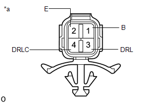
2. INSPECT CLEARANCE LIGHT ASSEMBLY RH
| (a) Apply battery voltage to the connector and check the light illumination condition. OK:
If the result is not as specified, replace the clearance light assembly RH. |
|

READ NEXT:
 Installation
INSTALLATION CAUTION / NOTICE / HINT HINT:
Use the same procedure for the RH and LH sides.
The procedure described below is for the LH side.
PROCEDURE 1. INSTALL CLEARANCE LIGHT ASSEMBLY LH (a
Components
COMPONENTS ILLUSTRATION *1 FOG LIGHT ASSEMBLY LH *2 FRONT BUMPER ASSEMBLY
SEE MORE:
A/C Inverter Cooling / Heating System Malfunction (B1475)
DESCRIPTION The temperature sensor of the compressor with motor assembly detects the A/C inverter temperature. If the temperature exceeds the maximum, operation of the compressor with motor assembly will be stopped, and this DTC will be stored. DTC No. Detection Item DTC Detection Condition
Problem Symptoms Table
PROBLEM SYMPTOMS TABLE HINT:
Use the table below to help determine the cause of problem symptoms. If multiple suspected areas are listed, the potential causes of the symptoms are listed in order of probability in the "Suspected Area" column of the table. Check each symptom by checking the suspect
