Lexus NX: Inspection
INSPECTION
PROCEDURE
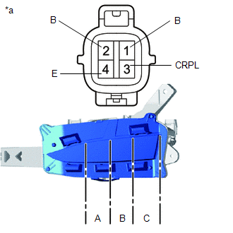
1. INSPECT FOG LIGHT ASSEMBLY LH
| (a) Apply battery voltage to the connector and check the light illumination condition. OK:
HINT: If the result is not as specified, replace the fog light assembly LH. |
|
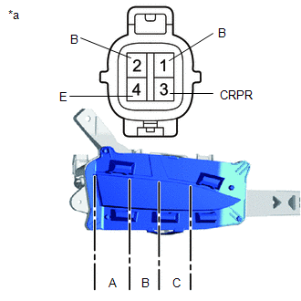
2. INSPECT FOG LIGHT ASSEMBLY RH
| (a) Apply battery voltage to the connector and check the light illumination condition. OK:
HINT: If the result is not as specified, replace the fog light assembly RH. |
|
READ NEXT:
 Adjustment
ADJUSTMENT CAUTION / NOTICE / HINT HINT:
Use the same procedure for the RH and LH sides.
The procedure listed below is for the LH side.
PROCEDURE 1. PREPARE VEHICLE FOR FOG LIGHT AIM ADJUSTMEN
Reassembly
REASSEMBLY CAUTION / NOTICE / HINT NOTICE:
Handle components indoors as much as possible to prevent foreign matter from entering and adhering to fog light assembly components.
Do not reuse parts
Installation
INSTALLATION CAUTION / NOTICE / HINT HINT:
Use the same procedure for the RH and LH sides.
The procedure described below is for the LH side.
PROCEDURE 1. INSTALL FOG LIGHT ASSEMBLY LH (a) Inst
SEE MORE:
Voltage Inverter
ComponentsCOMPONENTS ILLUSTRATION *1 DECK BOARD ASSEMBLY *2 DECK FLOOR BOX LH *3 NO. 2 DECK BOARD SUB-ASSEMBLY *4 NO. 3 DECK BOARD SUB-ASSEMBLY *5 REAR DECK FLOOR BOX - - ILLUSTRATION *1 DECK FLOOR BOX RH *2 NO. 1 TOOL BOX SUB-ASSEMBLY *3 NO. 2 TOOL
Ignition Coil And Spark Plug
ComponentsCOMPONENTS ILLUSTRATION *1 IGNITION COIL ASSEMBLY *2 NO. 1 ENGINE COVER SUB-ASSEMBLY *3 SPARK PLUG - - N*m (kgf*cm, ft.*lbf) : Specified torque - - RemovalREMOVAL PROCEDURE 1. REMOVE NO. 1 ENGINE COVER SUB-ASSEMBLY Click here 2. REMOVE IGNITION COIL
