Lexus NX: Inspection

INSPECTION

PROCEDURE

1. INSPECT HEADLIGHT DIMMER SWITCH ASSEMBLY

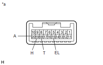
(a) Inspect the light control switch.

(1) Measure the resistance according to the value(s) in the table below.

Standard Resistance:

Tester Connection

Switch Condition

Specified Condition

*1: w/ Light Control Switch Off Position

*2: w/ Light control switch DRL OFF Position

18 (T) - 15 (EL)

Light control switch off*1

Light control switch DRL OFF*2

10 kΩ or higher

20 (A) - 15 (EL)

19 (H) - 15 (EL)

20 (A) - 15 (EL)

Light control switch AUTO position

Below 1 Ω

18 (T) - 15 (EL)

Light control switch tail position

Below 1 Ω

18 (T) - 15 (EL)

Light control switch head position

Below 1 Ω

19 (H) - 15 (EL)

HINT:

If the result is not as specified, replace the headlight dimmer switch assembly.

*a

Component without harness connected

(Headlight Dimmer Switch Assembly)

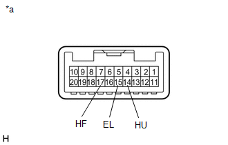
(b) Inspect the headlight dimmer switch.

(1) Measure the resistance according to the value(s) in the table below.

Standard Resistance:

Tester Connection

Switch Condition

Specified Condition

17 (HF) - 15 (EL)

Headlight dimmer switch flash position

Below 1 Ω

14 (HU) - 15 (EL)

14 (HU) - 15 (EL)

Headlight dimmer switch high position

Below 1 Ω

HINT:

If the result is not as specified, replace the headlight dimmer switch assembly.

*a

Component without harness connected

(Headlight Dimmer Switch Assembly)

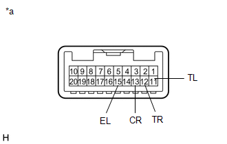
(c) Inspect the turn signal light switch.

(1) Measure the resistance according to the value(s) in the table below.

Standard Resistance:

Tester Connection

Switch Condition

Specified Condition

12 (TR) - 15 (EL)

Turn signal switch neutral position

10 kΩ or higher

11 (TL) - 15 (EL)

12 (TR) - 15 (EL)

Turn signal switch right turn position

(self cancel condition)

Below 1 Ω

12 (TR) - 15 (EL)

Turn signal switch right turn position

(cancel ratchet operation condition)

Below 1 Ω

12 (TR) - 13 (CR)

13 (CR) - 15 (EL)

11 (TL) - 15 (EL)

Turn signal switch left turn position

(self cancel condition)

Below 1 Ω

11 (TL) - 15 (EL)

Turn signal switch in left turn position

(cancel ratchet operation condition)

Below 1 Ω

11 (TL) - 13 (CR)

13 (CR) - 15 (EL)

HINT:

  • If the result is not as specified, replace the headlight dimmer switch assembly.
  • The self cancel condition indicates when the turn signal switch returns to the neutral position when releasing your hand from the switch (switch is operated within 7°).
  • The cancel ratchet operation condition indicates the condition when the turn signal switch does not return to the neutral position even when releasing your hand (switch operation is 12°).

*a

Component without harness connected

(Headlight Dimmer Switch Assembly)

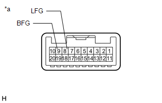
(d) Inspect the front fog light switch.

(1) Measure the resistance according to the value(s) in the table below.

Standard Resistance:

Tester Connection

Switch Condition

Specified Condition

9 (BFG) - 8 (LFG)

Front fog light switch off

10 kΩ or higher

9 (BFG) - 8 (LFG)

Front fog light switch on

Below 1 Ω

HINT:

If the result is not as specified, replace the headlight dimmer switch assembly.

*a

Component without harness connected

(Headlight Dimmer Switch Assembly)

READ NEXT:

 Installation

INSTALLATION PROCEDURE 1. INSTALL HEADLIGHT DIMMER SWITCH ASSEMBLY (a) Attach the 2 claws to install the headlight dimmer switch assembly. (b) Connect the connector. 2. INSTALL TILT AND TELESCOPIC SWI

 Headlight Ecu

 Precaution

PRECAUTION NOTICE: When disassembling the headlight assembly, use static electricity countermeasures SST (desktop antistatic mat set) and observe all precautions to prevent damage to the system by ele

SEE MORE:

 Display Malfunction (B15A6,B15B0)

DESCRIPTION These DTCs are stored when a malfunction occurs in the multi-display assembly. DTC No. Detection Item DTC Detection Condition Trouble Area B15A6 Display Malfunction When one of the conditions below is met: RAM error Drawing controller malfunction Multi-display

 How To Proceed With Troubleshooting

CAUTION / NOTICE / HINT HINT: Use these procedures to troubleshoot the adaptive variable suspension system. *: Use the Techstream. PROCEDURE 1. VEHICLE BROUGHT TO WORKSHOP NEXT 2. PROBLEM SYMPTOM CONFIRMATION NEXT 3. INSPECT AUXILIARY BATTERY

© 2016-2024 Copyright www.lexunx.com