Lexus NX: Inspection
INSPECTION
PROCEDURE
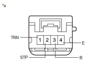
1. INSPECT REAR COMBINATION LIGHT ASSEMBLY LH
| (a) Apply battery voltage to the connector and check the light illumination condition. OK:
If the result is not as specified, replace the rear combination light assembly LH. |
|
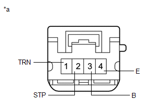
2. INSPECT REAR COMBINATION LIGHT ASSEMBLY RH
| (a) Apply battery voltage to the connector and check the light illumination condition. OK:
If the result is not as specified, replace the rear combination light assembly RH. |
|
READ NEXT:
 Reassembly
REASSEMBLY CAUTION / NOTICE / HINT HINT:
Use the same procedure for the RH and LH sides.
The procedure listed below is for the LH side.
PROCEDURE 1. INSTALL REAR COMBINATION LIGHT SOCKET AND W
Installation
INSTALLATION CAUTION / NOTICE / HINT HINT:
Use the same procedure for the RH and LH sides.
The procedure described below is for the LH side.
PROCEDURE 1. INSTALL REAR COMBINATION LIGHT ASSEMBL
SEE MORE:
Disposal
DISPOSAL PROCEDURE 1. DISPOSE OF BRAKE BOOSTER PUMP ASSEMBLY (a) Remove the accumulator from the brake booster pump assembly. (b) Secure the accumulator in a vise. (c) Using a hacksaw, make a cut in the side of the accumulator within location (A) to release the high-pressure gas. Location Le
Crankshaft Position Sensor
ComponentsCOMPONENTS ILLUSTRATION *1 CRANKSHAFT POSITION SENSOR - - N*m (kgf*cm, ft.*lbf) : Specified torque Toyota Genuine Adhesive 1324, Three Bond 1324 or equivalent ★ Precoated part - - RemovalREMOVAL PROCEDURE 1. REMOVE CRANKSHAFT POSITION SENSOR (a) Disc
