Lexus NX: Inspection
INSPECTION
PROCEDURE
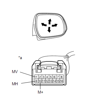
1. INSPECT OUTER REAR VIEW MIRROR ASSEMBLY LH
(a) Check the operation of the mirror surface.
| (1) Disconnect the outer rear view mirror assembly LH connector. |
|
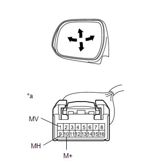
(2) Apply auxiliary battery voltage and check the operation of the mirror.
OK:
| Auxiliary Battery Connection | Specified Condition |
|---|---|
| Auxiliary battery positive (+) → 1 (MV) Auxiliary battery negative (-) → 10 (M+) | Turns upward |
| Auxiliary battery positive (+) → 10 (M+) Auxiliary battery negative (-) → 1 (MV) | Turns downward |
| Auxiliary battery positive (+) → 10 (M+) Auxiliary battery negative (-) → 9 (MH) | Turns right |
| Auxiliary battery negative (-) → 9 (MH) Auxiliary battery positive (+) → 10 (M+) | Turns left |
If the result is not as specified, replace the outer rear view mirror assembly LH.
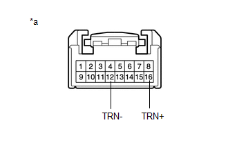
| (b) Check the side turn signal light assembly LH. (1) Apply auxiliary battery voltage to the terminals of the connector, and check the illumination condition. OK:
If the result is not as specified, replace the outer rear view mirror assembly LH. |
|
(c) Check the operation of the mirror heater.
| (1) Disconnect the outer rear view mirror assembly LH connector. |
|
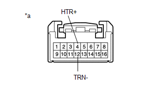
(2) Measure the resistance according to the value(s) in the table below.
Standard Resistance:
| Tester Connection | Condition | Specified Condition |
|---|---|---|
| 4 (HTR+) - 12 (TRN-) | 25°C (75°F) | 6.8 to 10.2 Ω |
If the result is not as specified, replace the outer rear view mirror assembly LH.
(3) Connect the cable from the positive (+) auxiliary battery terminal to terminal 4 and the negative (-) auxiliary battery terminal to terminal 12, and then check that the mirror becomes warm.
HINT:
It takes a short time for the mirror to become warm.
OK:
Mirror becomes warm.
If the result is not as specified, replace the outer rear view mirror assembly LH.
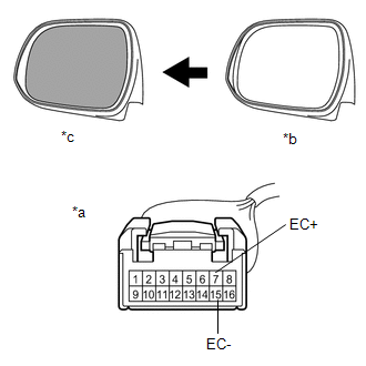
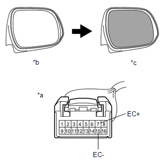
(d) w/ EC Mirror:
Check the EC mirror operation.
(1) Connect a new 1.5 V dry-cell battery.
| (2) Apply 1.5 V dry-cell battery voltage and check operation of the mirror face as shown in the table and illustration. OK:
NOTICE: Do not apply a voltage of 1.5 V or higher. If the result is not as specified, replace the outer rear view mirror assembly LH. |
|
| (e) w/ Blind Spot Monitor System: Check the operation of the blind spot monitor indicator. (1) Connect 4 new 1.5 V dry-cell batteries in series. (2) Apply 6 V dry-cell batteries to the terminals of the connector, and check the blind spot monitor indicator condition. OK:
If the result is not as specified, replace the outer rear view mirror assembly LH. |
|

2. INSPECT OUTER MIRROR RETRACTOR LH
(a) Check the operation of the retractable mirror.
NOTICE:
- Disconnect and reconnect the auxiliary battery between each mirror position check.
- The mirror position cannot be changed manually when the auxiliary battery is connected. To change the mirror position manually, the auxiliary battery must be disconnected first.
| (1) Disconnect the outer rear view mirror assembly LH connector. |
|
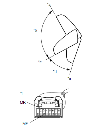
(2) For each position: Disconnect the auxiliary battery, set the mirror position by hand, connect the auxiliary battery, and check the retractable mirror movement.
OK:
| Auxiliary Battery Connection | Condition | Specified Condition |
|---|---|---|
| Auxiliary battery positive (+) → 3 (MR) Auxiliary battery negative (-) → 11 (MF) | Forward position (A) | Moves from (A) to (E) |
| Auxiliary battery positive (+) → 11 (MF) Auxiliary battery negative (-) → 3 (MR) | Forward position (A) | Does not move |
| Auxiliary battery positive (+) → 3 (MR) Auxiliary battery negative (-) → 11 (MF) | Position between forward position (A) and driving position (C) | Moves from (B) to (E) |
| Auxiliary battery positive (+) → 11 (MF) Auxiliary battery negative (-) → 3 (MR) | Position between forward position (A) and driving position (C) | Moves from (B) to (A) |
| Auxiliary battery positive (+) → 3 (MR) Auxiliary battery negative (-) → 11 (MF) | Driving position (C) | Moves from (C) to (E) |
| Auxiliary battery positive (+) → 11 (MF) Auxiliary battery negative (-) → 3 (MR) | Driving position (C) | Does not move |
| Auxiliary battery positive (+) → 3 (MR) Auxiliary battery negative (-) → 11 (MF) | Position between driving position (C) and retracted position (E) | Moves from (D) to (E) |
| Auxiliary battery positive (+) → 11 (MF) Auxiliary battery negative (-) → 3 (MR) | Position between driving position (C) and retracted position (E) | Moves from (D) to (C) |
| Auxiliary battery positive (+) → 3 (MR) Auxiliary battery negative (-) → 11 (MF) | Retracted position (E) | Does not move |
| Auxiliary battery positive (+) → 11 (MF) Auxiliary battery negative (-) → 3 (MR) | Retracted position (E) | Moves from (E) to (C) |
If the result is not as specified, replace the outer mirror retractor LH.
3. INSPECT OUTER REAR VIEW MIRROR ASSEMBLY RH
(a) Check the operation of the mirror surface.
| (1) Disconnect the outer rear view mirror assembly RH connector. |
|
(2) Apply auxiliary battery voltage and check the operation of the mirror.
OK:
| Auxiliary Battery Connection | Specified Condition |
|---|---|
| Auxiliary battery positive (+) → 1 (MV) Auxiliary battery negative (-) → 10 (M+) | Turns upward |
| Auxiliary battery positive (+) → 10 (M+) Auxiliary battery negative (-) → 1 (MV) | Turns downward |
| Auxiliary battery positive (+) → 9 (MH) Auxiliary battery negative (-) → 10 (M+) | Turns left |
| Auxiliary battery positive (+) → 10 (M+) Auxiliary battery negative (-) → 9 (MH) | Turns right |
If the result is not as specified, replace the outer rear view mirror assembly RH.
| (b) Check the side turn signal light assembly RH. (1) Apply auxiliary battery voltage to the terminals of the connector, and check the illumination condition. OK:
If the result is not as specified, replace the outer rear view mirror assembly RH. |
|
(c) Check the operation of the mirror heater.
| (1) Disconnect the outer rear view mirror assembly RH connector. |
|
(2) Measure the resistance according to the value(s) in the table below.
Standard Resistance:
| Tester Connection | Condition | Specified Condition |
|---|---|---|
| 4 (HTR+) - 12 (TRN-) | 25°C (75°F) | 6.8 to 10.2 Ω |
If the result is not as specified, replace the outer rear view mirror assembly RH.
(3) Connect the cable from the positive (+) auxiliary battery terminal to terminal 4 and the negative (-) auxiliary battery terminal to terminal 12, and then check that the mirror becomes warm.
HINT:
It takes a short time for the mirror to become warm.
OK:
Mirror becomes warm.
If the result is not as specified, replace the outer rear view mirror assembly RH.
(d) w/ EC Mirror:
Check the EC mirror operation.
(1) Connect a new 1.5 V dry-cell battery.
| (2) Apply 1.5 V dry-cell battery voltage and check operation of the mirror face as shown in the table and illustration. OK:
NOTICE: Do not apply a voltage of 1.5 V or higher. If the result is not as specified, replace the outer rear view mirror assembly RH. |
|
| (e) w/ Blind Spot Monitor System: Check the operation of the blind spot monitor indicator. (1) Connect 4 new 1.5 V dry-cell batteries in series. (2) Apply 6 V dry-cell batteries to the terminals of the connector, and check the blind spot monitor indicator condition. OK:
If the result is not as specified, replace the outer rear view mirror assembly RH. |
|

4. INSPECT OUTER MIRROR RETRACTOR RH
(a) Check the operation of the retractable mirror.
NOTICE:
- Disconnect and reconnect the auxiliary battery between each mirror position check.
- The mirror position cannot be changed manually when the auxiliary battery is connected. To change the mirror position manually, the auxiliary battery must be disconnected first.
| (1) Disconnect the outer rear view mirror assembly RH connector. |
|
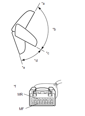
(2) For each position: Disconnect the auxiliary battery, set the mirror position by hand, connect the auxiliary battery, and check the retractable mirror movement.
OK:
| Auxiliary Battery Connection | Condition | Specified Condition |
|---|---|---|
| Auxiliary battery positive (+) → 3 (MR) Auxiliary battery negative (-) → 11 (MF) | Forward position (A) | Moves from (A) to (E) |
| Auxiliary battery positive (+) → 11 (MF) Auxiliary battery negative (-) → 3 (MR) | Forward position (A) | Does not move |
| Auxiliary battery positive (+) → 3 (MR) Auxiliary battery negative (-) → 11 (MF) | Position between forward position (A) and driving position (C) | Moves from (B) to (E) |
| Auxiliary battery positive (+) → 11 (MF) Auxiliary battery negative (-) → 3 (MR) | Position between forward position (A) and driving position (C) | Moves from (B) to (A) |
| Auxiliary battery positive (+) → 3 (MR) Auxiliary battery negative (-) → 11 (MF) | Driving position (C) | Moves from (C) to (E) |
| Auxiliary battery positive (+) → 11 (MF) Auxiliary battery negative (-) → 3 (MR) | Driving position (C) | Does not move |
| Auxiliary battery positive (+) → 3 (MR) Auxiliary battery negative (-) → 11 (MF) | Position between driving position (C) and retracted position (E) | Moves from (D) to (E) |
| Auxiliary battery positive (+) → 11 (MF) Auxiliary battery negative (-) → 3 (MR) | Position between driving position (C) and retracted position (E) | Moves from (D) to (C) |
| Auxiliary battery positive (+) → 3 (MR) Auxiliary battery negative (-) → 11 (MF) | Retracted position (E) | Does not move |
| Auxiliary battery positive (+) → 11 (MF) Auxiliary battery negative (-) → 3 (MR) | Retracted position (E) | Moves from (E) to (C) |
If the result is not as specified, replace the outer mirror retractor RH.
READ NEXT:
 Reassembly
REASSEMBLY CAUTION / NOTICE / HINT HINT:
Use the same procedure for the RH and LH sides.
The procedure listed below is for the LH side.
PROCEDURE 1. INSTALL OUTER MIRROR RETRACTOR LH (a) In
Installation
INSTALLATION CAUTION / NOTICE / HINT HINT:
Use the same procedure for the RH and LH sides.
The procedure listed below is for the LH side.
PROCEDURE 1. INSTALL OUTER REAR VIEW MIRROR ASSEMBLY L
SEE MORE:
Inspection
INSPECTION PROCEDURE 1. INSPECT SEPARATE TYPE FRONT SEATBACK COVER LH *a Component without harness connected (Separate Type Front Seatback Cover LH (Front Seatback Heater)) (a) Check the separate type front seatback cover LH (front seatback heater). (1) Measure the resistance according to t
Dtc Check / Clear
DTC CHECK / CLEAR DTC CHECK (a) Turn the power switch off. (b) Connect the Techstream to the DLC3. (c) Turn the power switch on (IG). (d) Turn the Techstream on. (e) Enter the following menus: Body Electrical / Occupant Detection / Trouble Codes. (f) Check for DTCs by following the prompts on the Te
