Lexus NX: Inspection
INSPECTION
PROCEDURE
1. INSPECT POWER WINDOW REGULATOR MOTOR ASSEMBLY LH
NOTICE:
- Do not apply voltage to any terminals except terminals 1 and 2 to avoid damaging the pulse sensor inside the motor.
-
Reset the power window regulator motor (initialize the pulse sensor) after installing the power window regulator motor and regulator assembly to the door.
Click here
.gif)
| (a) Apply positive (+) auxiliary battery voltage to the connector terminal 2 (B). |
|
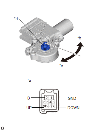
(b) Apply negative (-) auxiliary battery voltage to the connector terminals 1 (GND) and 7 (DOWN)/10 (UP).
(c) Check that the motor gear rotates smoothly as follows.
OK:
| Measurement Condition | Specified Condition |
|---|---|
| Auxiliary battery positive (+) → 2 (B) Auxiliary battery negative (-): 1 (GND) (3 seconds or more) → 1 (GND) and 10 (UP) (within 1 second) → 1 (GND) (within 1 second) → 1 (GND) and 10 (UP) | Motor gear rotates clockwise (UP) |
| Auxiliary battery positive (+) → 2 (B) Auxiliary battery negative (-): 1 (GND) (3 seconds or more) → 1 (GND) and 7 (DOWN) (within 1 second) → 1 (GND) (within 1 second) → 1 (GND) and 7 (DOWN) | Motor gear rotates counterclockwise (DOWN) |
2. INSPECT POWER WINDOW REGULATOR MOTOR ASSEMBLY RH
NOTICE:
- Do not apply voltage to any terminals except terminals 1 and 2 to avoid damaging the pulse sensor inside the motor.
-
Reset the power window regulator motor (initialize the pulse sensor) after installing the power window regulator motor and regulator assembly to the door.
Click here
| (a) Apply positive (+) auxiliary battery voltage to the connector terminal 2 (B). |
|
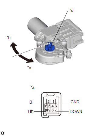
(b) Apply negative (-) auxiliary battery voltage to the connector terminals 1 (GND) and 7 (DOWN)/10 (UP).
(c) Check that the motor gear rotates smoothly as follows.
OK:
| Measurement Condition | Specified Condition |
|---|---|
| Auxiliary battery positive (+) → 2 (B) Auxiliary battery negative (-): 1 (GND) (3 seconds or more) → 1 (GND) and 10 (UP) (within 1 second) → 1 (GND) (within 1 second) → 1 (GND) and 10 (UP) | Motor gear rotates clockwise (UP) |
| Auxiliary battery positive (+) → 2 (B) Auxiliary battery negative (-): 1 (GND) (3 seconds or more) → 1 (GND) and 7 (DOWN) (within 1 second) → 1 (GND) (within 1 second) → 1 (GND) and 7 (DOWN) | Motor gear rotates counterclockwise (DOWN) |
READ NEXT:
 Installation
INSTALLATION CAUTION / NOTICE / HINT HINT:
Use the same procedure for the RH and LH sides.
The procedure listed below is for the LH side.
A bolt without a torque specification is shown in the s
Components
COMPONENTS ILLUSTRATION *1 DECK FLOOR BOX LH *2 NO. 3 DECK BOARD SUB-ASSEMBLY *3 REAR DECK FLOOR BOX *4 NEGATIVE AUXILIARY BATTERY TERMINAL N*m (kgf*cm, ft.*lbf): Specified
SEE MORE:
Engine Immobiliser System Communication Line High Fixation (B279A-186)
DESCRIPTION When the communication line (IMI - EFIO) between the hybrid vehicle control ECU and ID code box (immobiliser code ECU) is stuck high, the hybrid vehicle control ECU stores this DTC. DTC No. Detection Item DTC Detection Condition Trouble Area Note B279A-186 Engine Immobil
Power Back Door Control Switch
ComponentsCOMPONENTS ILLUSTRATION *1 BACK DOOR CONTROL SWITCH *2 PULL HANDLE RemovalREMOVAL PROCEDURE 1. REMOVE PULL HANDLE Click here 2. REMOVE BACK DOOR CONTROL SWITCH (a) Detach the 2 claws and remove the back door control switch. InspectionINSPECTION PROCEDURE 1.
