Lexus NX: Inspection
INSPECTION
PROCEDURE
1. INSPECT REAR DOOR LOCK ASSEMBLY LH
| (a) Check the door lock motor operation. (1) Apply auxiliary battery voltage to the motor connector and check the operation of the door lock motor. OK:
If the result is not as specified, replace the rear door lock assembly LH. |
|
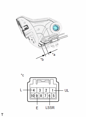
(b) Check the operation of the door unlock detection switch.
(1) Measure the resistance according to the value(s) in the table below.
Standard Resistance:
| Tester Connection | Condition | Specified Condition |
|---|---|---|
| 6 (LSSR) - 9 (E) | Lock | 10 kΩ or higher |
| 6 (LSSR) - 9 (E) | Unlock | Below 1 Ω |
If the result is not as specified, replace the rear door lock assembly LH.
2. INSPECT REAR DOOR LOCK ASSEMBLY RH
| (a) Check the door lock motor operation. (1) Apply auxiliary battery voltage to the motor connector and check the operation of the door lock motor. OK:
If the result is not as specified, replace the rear door lock assembly RH. |
|
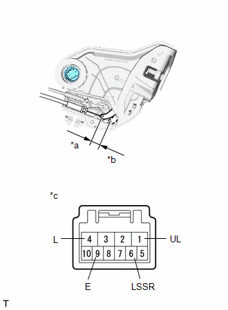
(b) Check the operation of the unlock detection switch.
(1) Measure the resistance according to the value(s) in the table below.
Standard Resistance:
| Tester Connection | Condition | Specified Condition |
|---|---|---|
| 6 (LSSR) - 9 (E) | Lock | 10 kΩ or higher |
| 6 (LSSR) - 9 (E) | Unlock | Below 1 Ω |
If the result is not as specified, replace the rear door lock assembly RH.
READ NEXT:
 Installation
INSTALLATION CAUTION / NOTICE / HINT HINT:
Use the same procedure for the RH and LH sides.
The procedure listed below is for the LH side.
A bolt without a torque specification is shown in the s
Transmitter Battery
ReplacementREPLACEMENT PROCEDURE 1. REMOVE TRANSMITTER BATTERY (a) Push the release hook knob and extract the mechanical key. (b) Using a screwdriver with its tip wrapped in protect
Wireless Door Lock Buzzer
ComponentsCOMPONENTS ILLUSTRATION *1 FRONT FENDER SPLASH SHIELD FRONT LH *2 WIRELESS DOOR LOCK BUZZER *3 FRONT SIDE AIR GUIDE SUB-ASSEMBLY LH *4 FRONT FENDER LINER LH Installa
SEE MORE:
Visual Mute Signal Circuit between Radio Receiver and Multi-display
DESCRIPTION The radio receiver assembly sends a visual mute signal to the multi-display assembly. As a result, a black screen is inserted when the screen changes so that noise and distorted images are not displayed. When an open exists in the circuit, noise and distorted images will be displayed ins
Installation
INSTALLATION CAUTION / NOTICE / HINT HINT:
Use the same procedure for the RH and LH sides.
The procedure described below is for the LH side.
PROCEDURE 1. INSTALL HEADLIGHT ASSEMBLY LH (a) Connect the connector and lock the connector lock lever. *a Connector Lock Lever Connect th
