Lexus NX: Inspection
INSPECTION
PROCEDURE
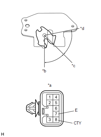
1. INSPECT BACK DOOR LOCK ASSEMBLY (BACK DOOR COURTESY SWITCH)
(a) w/o Power Back Door:
| (1) Move the back door lock assembly to the lock position. |
|
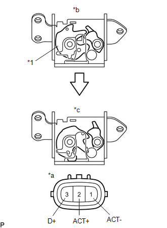
(2) Measure the resistance according to the value(s) in the table below.
Standard Resistance:
| Tester Connection | Condition | Specified Condition |
|---|---|---|
| 1 (ACT-) - 3 (D+) | Lock | 10 kΩ or higher |
(3) Apply battery voltage to the door lock motor and check the operation of the door lock motor.
OK:
| Tester Connection | Condition | Specified Condition |
|---|---|---|
| 2 (ACT+) - 1 (ACT-) | Battery positive (+) → 2 (ACT+) Battery negative (-) → 1 (ACT-) | Unlock |
(4) Measure the resistance according to the value(s) in the table below.
Standard Resistance:
| Tester Connection | Condition | Specified Condition |
|---|---|---|
| 1 (ACT-) - 3 (D+) | Unlock | Below 1 Ω |
(b) w/ Power Back Door:
| (1) Apply battery voltage to the door lock motor and check the operation of the door lock motor. OK:
|
|
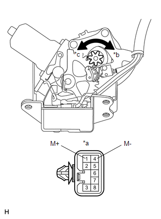
| (2) Measure the resistance according to the value(s) in the table below. Standard Resistance:
If the result is not as specified, replace the back door lock assembly (back door courtesy switch). |
|
READ NEXT:
 Installation
INSTALLATION PROCEDURE 1. INSTALL BACK DOOR LOCK ASSEMBLY (BACK DOOR COURTESY SWITCH) HINT:
When installing a new back door lock assembly (back door courtesy switch), if there is a rope on the asse
Components
COMPONENTS ILLUSTRATION *A w/ Wireless Charger *B w/o Wireless Charger *1 CONSOLE BOX ASSEMBLY *2 CONSOLE BOX ILLUMINATION LIGHT ASSEMBLY *3 CONSOLE COMPARTMENT DOOR SUB-ASSE
SEE MORE:
Diagnostic Trouble Code Chart
DIAGNOSTIC TROUBLE CODE CHART Front Power Seat Control System (w/ Memory) DTC No. Detection Item Link B2650 Slide Sensor Malfunction B2658 Short in Sensor with Motor Power Supply Circuit
Diagnostic Trouble Code Chart
DIAGNOSTIC TROUBLE CODE CHART CAN Communication System DTC No. Detection Item DTC Output from Link B1003 ECU Malfunction Central gateway ECU (network gateway ECU) U0199 Lost Communication with "Door Control Module A" Main Body U0200 Lost Communication with "D
