Lexus NX: Inspection
INSPECTION
PROCEDURE
1. INSPECT FRONT POWER SEAT SWITCH LH (w/o Memory)
| (a) Measure the resistance according to the value(s) in the tables below. Standard Resistance (Slide Switch): | Tester Connection | Switch Condition | Specified Condition | | 5 (SLDF) - 8 (B) 5 (SLDF) - 7 (B1) | Front position | Below 1 Ω | | 2 (SLDR) - 11 (E) 2 (SLDR) - 12 (E1) | | 5 (SLDF) - 11 (E) 5 (SLDF) - 12 (E1) | Neutral | Below 1 Ω | | 2 (SLDR) - 11 (E) 2 (SLDR) - 12 (E1) | | 5 (SLDF) - 11 (E) 5 (SLDF) - 12 (E1) | Rear position | Below 1 Ω | | 2 (SLDR) - 8 (B) 2 (SLDR) - 7 (B1) | Standard Resistance (Front Vertical Switch): | Tester Connection | Switch Condition | Specified Condition | | 1 (FUP) - 8 (B) 1 (FUP) - 7 (B1) | Up position | Below 1 Ω | | 6 (FDWN) - 11 (E) 6 (FDWN) - 12 (E1) | | 1 (FUP) - 11 (E) 1 (FUP) - 12 (E1) | Neutral | Below 1 Ω | | 6 (FDWN) - 11 (E) 6 (FDWN) - 12 (E1) | | 1 (FUP) - 11 (E) 1 (FUP) - 12 (E1) | Down position | Below 1 Ω | | 6 (FDWN) - 8 (B) 6 (FDWN) - 7 (B1) | Standard Resistance (Lifter Switch): | Tester Connection | Switch Condition | Specified Condition | | 3 (LUP) - 8 (B) 3 (LUP) - 7 (B1) | Up position | Below 1 Ω | | 4 (LDWN) - 11 (E) 4 (LDWN) - 12 (E1) | | 3 (LUP) - 11 (E) 3 (LUP) - 12 (E1) | Neutral | Below 1 Ω | | 4 (LDWN) - 11 (E) 4 (LDWN) - 12 (E1) | | 3 (LUP) - 11 (E) 3 (LUP) - 12 (E1) | Down position | Below 1 Ω | | 4 (LDWN) - 8 (B) 4 (LDWN) - 7 (B1) | Standard Resistance (Reclining Switch): | Tester Connection | Switch Condition | Specified Condition | | 8 (B) - 10 (RCLF) 7 (B1) - 10 (RCLF) | Front position | Below 1 Ω | | 9 (RCLR) - 11 (E) 9 (RCLR) - 12 (E1) | | 10 (RCLF) - 11 (E) 10 (RCLF) - 12 (E1) | Neutral | Below 1 Ω | | 9 (RCLR) - 11 (E) 9 (RCLR) - 12 (E1) | | 10 (RCLF) - 11 (E) 10 (RCLF) - 12 (E1) | Rear position | Below 1 Ω | | 8 (B) - 9 (RCLR) 7 (B1) - 9 (RCLR) | If the result is not as specified, replace the front power seat switch LH. | 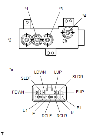 | | *1 | Slide Switch | | *2 | Front Vertical Switch | | *3 | Lifter Switch | | *4 | Reclining Switch | | *a | Component without harness connected (Front Power Seat Switch LH) | | |
2. INSPECT FRONT POWER SEAT SWITCH RH (w/o Memory)
| (a) Measure the resistance according to the value(s) in the tables below. Standard Resistance (Slide Switch): | Tester Connection | Switch Condition | Specified Condition | | 2 (SLDF) - 13 (B) | Front position | Below 1 Ω | | 5 (SLDR) - 10 (E) | | 2 (SLDF) - 10 (E) | Neutral | Below 1 Ω | | 5 (SLDR) - 10 (E) | | 2 (SLDF) - 10 (E) | Rear position | Below 1 Ω | | 5 (SLDR) - 13 (B) | Standard Resistance (Front Vertical Switch): | Tester Connection | Switch Condition | Specified Condition | | 6 (FUP) - 13 (B) | Up position | Below 1 Ω | | 1 (FDWN) - 10 (E) | | 6 (FUP) - 10 (E) | Neutral | Below 1 Ω | | 1 (FDWN) - 10 (E) | | 6 (FUP) - 10 (E) | Down position | Below 1 Ω | | 1 (FDWN) - 13 (B) | Standard Resistance (Lifter Switch): | Tester Connection | Switch Condition | Specified Condition | | 4 (LUP) - 13 (B) | Up position | Below 1 Ω | | 3 (LDWN) - 10 (E) | | 4 (LUP) - 10 (E) | Neutral | Below 1 Ω | | 3 (LDWN) - 10 (E) | | 4 (LUP) - 10 (E) | Down position | Below 1 Ω | | 3 (LDWN) - 13 (B) | Standard Resistance (Reclining Switch): | Tester Connection | Switch Condition | Specified Condition | | 11 (RCLF) - 13 (B) | Front position | Below 1 Ω | | 12 (RCLR) - 10 (E) | | 11 (RCLF) - 10 (E) | Neutral | Below 1 Ω | | 12 (RCLR) - 10 (E) | | 11 (RCLF) - 10 (E) | Rear position | Below 1 Ω | | 12 (RCLR) - 13 (B) | If the result is not as specified, replace the front power seat switch RH. | 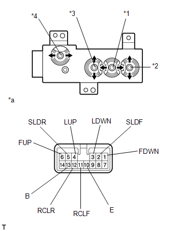 | | *1 | Slide Switch | | *2 | Front Vertical Switch | | *3 | Lifter Switch | | *4 | Reclining Switch | | *a | Component without harness connected (Front Power Seat Switch RH) | | |
READ NEXT:
INSTALLATION CAUTION / NOTICE / HINT HINT:
Use the same procedure for the RH and LH sides.
The procedure listed below is for the LH side.
PROCEDURE 1. INSTALL FRONT POWER SEAT SWITCH LH (a) In
COMPONENTS ILLUSTRATION *A for Front Side - - *1 CONSOLE ARMREST ASSEMBLY *2 COWL SIDE TRIM BOARD LH *3 DOOR SCUFF PLATE ASSEMBLY LH *4 INSTRUMENT SIDE PANEL LH *5
SEE MORE:
PRECAUTION FOR OPERATION OF ELECTRICAL ITEMS RESTRICTED NOTICE:
If the auxiliary battery voltage is low, the climate control seat system may not operate. When "High Power Consumption / Partial Limit On AC/Heater Operation" is displayed on the multi-information display in the combination meter ass
INSTALLATION CAUTION / NOTICE / HINT HINT: Perform "Inspection After Repairs" after replacing the cylinder head sub-assembly. Click here PROCEDURE 1. INSTALL CYLINDER HEAD GASKET (a) Clean the cylinder block and cylinder head sub-assembly with solvent. (b) Apply a seal packing to a new cylinder he
© 2016-2024 Copyright www.lexunx.com

 Installation