Lexus NX: Inspection
INSPECTION
PROCEDURE
1. INSPECT SPIRAL WITH SENSOR CABLE SUB-ASSEMBLY
NOTICE:
- Do not remove the steering sensor from the spiral with sensor cable sub-assembly.
- As the spiral with sensor cable sub-assembly may break, do not rotate the spiral with sensor cable sub-assembly more than the specified amount.
(a) Visually check for defects with the spiral with sensor cable sub-assembly.
(1) The defects are as follows:
- Scratches
- Small cracks
- Dents
- Chips
- Cracks or other damage to the connector
OK:
No defects are found.
If any of the defects is found, replace the spiral with sensor cable sub-assembly with a new one.
(b) Check the spiral with sensor cable sub-assembly.
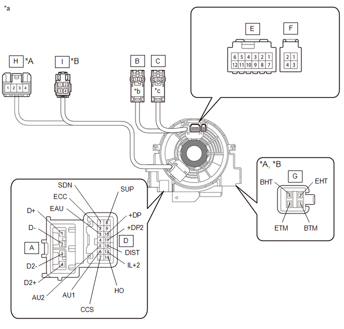
| *A | w/ Steering Heater, w/ Steering Vibration | *B | w/ Steering Heater, w/o Steering Vibration |
| *a | Component without harness connected (Spiral Cable sub-assembly) | *b | Color: Light Green |
| *c | Color: Black | - | - |
 | Interlock | - | - |
NOTICE:
When rotating the spiral with sensor cable sub-assembly, make sure to push on the interlock indicated in the illustration to release the interlock mechanism.
(1) Set the spiral with sensor cable sub-assembly to the center position.
Click here .gif)
(2) Measure the resistance between each terminal of the spiral with sensor cable sub-assembly according to the table below.
Standard Resistance:
| Tester Connection | Condition | Specified Condition |
|---|---|---|
|
*A: w/ Steering Heater, w/o Steering Vibration
*B: w/ Steering Heater, w/ Steering Vibration | ||
| A-1 (D+) - B-2 | Always | Below 1 Ω |
| A-2 (D-) - B-1 | Always | Below 1 Ω |
| A-3 (D2-) - C-1 | Always | Below 1 Ω |
| A-4 (D2+) - C-2 | Always | Below 1 Ω |
| D-1 (SDN) - F-3 | Always | 3 Ω or less |
| D-2 (ECC) - F-4 | Always | 3 Ω or less |
| D-3 (EAU) - E-8 | Always | 3 Ω or less |
| D-5 (AU2) - E-10 | Always | 3 Ω or less |
| D-6 (AU1) - E-11 | Always | 3 Ω or less |
| D-7 (CCS) - E-12 | Always | 3 Ω or less |
| D-8 (SUP) - F-1 | Always | 3 Ω or less |
| D-10 (+DP) - E-2 | Always | 3 Ω or less |
| D-11 (+DP2) - E-3 | Always | 3 Ω or less |
| D-12 (DIST) - E-4 | Always | 3 Ω or less |
| D-13 (IL+2) - E-5 | Always | 3 Ω or less |
| D-14 (HO) - E-6 | Always | 3 Ω or less |
| G-1 (BTM) - I-1*A | Always | Below 0.1 Ω |
| G-2 (EHT) - I-3*A | Always | Below 0.1 Ω |
| G-3 (ETM) - I-2*A | Always | Below 0.1 Ω |
| G-4 (BHT) - I-4*A | Always | Below 0.1 Ω |
| G-1 (BTM) - H-2*B | Always | Below 0.1 Ω |
| G-2 (EHT) - H-1*B | Always | Below 0.1 Ω |
| G-3 (ETM) - H-3*B | Always | Below 0.1 Ω |
| G-4 (BHT) - H-4*B | Always | Below 0.1 Ω |
(3) After setting the spiral with sensor cable sub-assembly to the center position, rotate the spiral with sensor cable sub-assembly 2.5 times clockwise, and measure the resistance as shown in the table below. Then rotate the spiral with sensor cable sub-assembly 5 times counterclockwise, and measure the resistance as shown in the table below.
Standard Resistance:
| Tester Connection | Condition | Specified Condition |
|---|---|---|
|
*A: w/ Steering Heater, w/o Steering Vibration
*B: w/ Steering Heater, w/ Steering Vibration | ||
| A-1 (D+) - B-2 | Always | Below 1 Ω |
| A-2 (D-) - B-1 | Always | Below 1 Ω |
| A-3 (D2-) - C-1 | Always | Below 1 Ω |
| A-4 (D2+) - C-2 | Always | Below 1 Ω |
| D-1 (SDN) - F-3 | Always | 3 Ω or less |
| D-2 (ECC) - F-4 | Always | 3 Ω or less |
| D-3 (EAU) - E-8 | Always | 3 Ω or less |
| D-5 (AU2) - E-10 | Always | 3 Ω or less |
| D-6 (AU1) - E-11 | Always | 3 Ω or less |
| D-7 (CCS) - E-12 | Always | 3 Ω or less |
| D-8 (SUP) - F-1 | Always | 3 Ω or less |
| D-10 (+DP) - E-2 | Always | 3 Ω or less |
| D-11 (+DP2) - E-3 | Always | 3 Ω or less |
| D-12 (DIST) - E-4 | Always | 3 Ω or less |
| D-13 (IL+2) - E-5 | Always | 3 Ω or less |
| D-14 (HO) - E-6 | Always | 3 Ω or less |
| G-1 (BTM) - I-1*A | Always | Below 0.1 Ω |
| G-2 (EHT) - I-3*A | Always | Below 0.1 Ω |
| G-3 (ETM) - I-2*A | Always | Below 0.1 Ω |
| G-4 (BHT) - I-4*A | Always | Below 0.1 Ω |
| G-1 (BTM) - H-2*B | Always | Below 0.1 Ω |
| G-2 (EHT) - H-1*B | Always | Below 0.1 Ω |
| G-3 (ETM) - H-3*B | Always | Below 0.1 Ω |
| G-4 (BHT) - H-4*B | Always | Below 0.1 Ω |
(4) After setting the spiral with sensor cable sub-assembly to the center position, rotate the spiral with sensor cable sub-assembly 2.5 times clockwise. Then while rotating the spiral with sensor cable sub-assembly 5 times counterclockwise, measure the resistance as shown in the table below.
If the result is not as specified, replace the spiral with sensor cable sub-assembly.
Standard Resistance:
| Tester Connection | Condition | Specified Condition |
|---|---|---|
|
*A: w/ Steering Heater, w/o Steering Vibration
*B: w/ Steering Heater, w/ Steering Vibration | ||
| A-1 (D+) - B-2 | Always | Below 1 Ω |
| A-2 (D-) - B-1 | Always | Below 1 Ω |
| A-3 (D2-) - C-1 | Always | Below 1 Ω |
| A-4 (D2+) - C-2 | Always | Below 1 Ω |
| D-1 (SDN) - F-3 | Always | 3 Ω or less |
| D-2 (ECC) - F-4 | Always | 3 Ω or less |
| D-3 (EAU) - E-8 | Always | 3 Ω or less |
| D-5 (AU2) - E-10 | Always | 3 Ω or less |
| D-6 (AU1) - E-11 | Always | 3 Ω or less |
| D-7 (CCS) - E-12 | Always | 3 Ω or less |
| D-8 (SUP) - F-1 | Always | 3 Ω or less |
| D-10 (+DP) - E-2 | Always | 3 Ω or less |
| D-11 (+DP2) - E-3 | Always | 3 Ω or less |
| D-12 (DIST) - E-4 | Always | 3 Ω or less |
| D-13 (IL+2) - E-5 | Always | 3 Ω or less |
| D-14 (HO) - E-6 | Always | 3 Ω or less |
| G-1 (BTM) - I-1*A | Always | Below 0.1 Ω |
| G-2 (EHT) - I-3*A | Always | Below 0.1 Ω |
| G-3 (ETM) - I-2*A | Always | Below 0.1 Ω |
| G-4 (BHT) - I-4*A | Always | Below 0.1 Ω |
| G-1 (BTM) - H-2*B | Always | Below 0.1 Ω |
| G-2 (EHT) - H-1*B | Always | Below 0.1 Ω |
| G-3 (ETM) - H-3*B | Always | Below 0.1 Ω |
| G-4 (BHT) - H-4*B | Always | Below 0.1 Ω |
READ NEXT:
 Components
COMPONENTS ILLUSTRATION *1 DECK FLOOR BOX LH *2 NO. 3 DECK BOARD SUB-ASSEMBLY *3 REAR DECK FLOOR BOX *4 AUXILIARY BATTERY NEGATIVE TERMINAL N*m (kgf*cm, ft.*lbf): Specified
On-vehicle Inspection
ON-VEHICLE INSPECTION CAUTION / NOTICE / HINT CAUTION: Be sure to follow the correct removal and installation procedures of the front seat cushion airbag assembly RH. HINT:
Use the same procedure f
SEE MORE:
Components
COMPONENTS ILLUSTRATION *A w/ AVS - - *1 REAR AXLE HUB AND BEARING ASSEMBLY LH *2 REAR AXLE SHAFT NUT LH *3 REAR DISC *4 REAR DISC BRAKE CALIPER ASSEMBLY LH *5 REAR SPEED SENSOR LH *6 REAR DISC BRAKE DUST COVER SUB-ASSEMBLY LH N*m (kgf*cm, ft.*lbf): Spe
Back Door Entry Lock and Unlock Functions do not Operate
DESCRIPTION If the entry lock and unlock functions do not operate for the back door only, the request code may not be being transmitted from the back door. If the entry functions for other doors operate properly, communication between the electrical key transmitter sub-assembly and door control rece
