Lexus NX: Inspection
INSPECTION
PROCEDURE
1. INSPECT INTEGRATION CONTROL AND PANEL ASSEMBLY
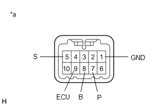
| (a) Measure the resistance according to the value(s) in the table below. Standard Resistance:
If the result is not as specified, replace the integration control and panel assembly. |
|
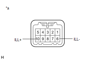
| (b) Apply battery voltage between the terminals of the switch, and check the illumination condition of the integration control and panel assembly. Standard:
If the result is not as specified, replace the integration control and panel assembly. |
|
READ NEXT:
 Installation
INSTALLATION PROCEDURE 1. INSTALL INTEGRATION CONTROL AND PANEL ASSEMBLY (a) Install the integration control and panel assembly to the rear upper console panel sub-assembly with the 2 screws. HINT:
On-vehicle Inspection
ON-VEHICLE INSPECTION PROCEDURE 1. REMOVE NO. 1 ENGINE UNDER COVER ASSEMBLY Click here 2. INSPECT HYBRID TRANSAXLE FLUID (a) Using a 10 mm hexagon socket wrench, remove the filler plug and gask
SEE MORE:
Green Indicator Remains Off
DESCRIPTION After power switch on (IG), the DCM (telematics transceiver) will enter into self check mode. The manual (SOS) switch red indicator will illuminate for 2 seconds and turn off followed by the manual (SOS) switch green indicator illuminating and remaining on under normal operation. If neit
Installation
INSTALLATION PROCEDURE 1. INSTALL NO. 4 FUEL TUBE CLAMP (a) Install the 5 No. 4 fuel tube clamps to the fuel tank assembly as shown in the illustration. 2. INSTALL FUEL TANK MAIN TUBE SUB-ASSEMBLY (a) Connect the 5 clamps and install the fuel tank main tube sub-assembly to the 5 No. 4
