Lexus NX: Inspection
INSPECTION
PROCEDURE
1. INSPECT SHIFT LOCK CONTROL ECU
| (a) Measure the voltage according to the value(s) in the table below. Standard Voltage:
HINT: Do not disconnect the shift lock control unit assembly connector. If the result is not as specified, replace the shift lock control unit assembly. |
|
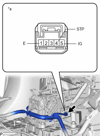
(b) Measure the resistance according to the value(s) in the table below.
Standard Resistance:
| Tester Connection | Condition | Specified Condition |
|---|---|---|
| 1 (E) - Body ground | Always | Below 1 Ω |
HINT:
Do not disconnect the shift lock control unit assembly connector.
If the result is not as specified, replace the shift lock control unit assembly.
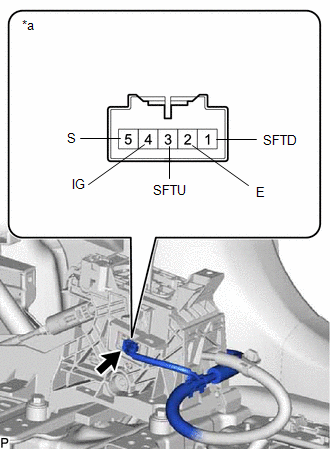
2. INSPECT TRANSMISSION CONTROL SWITCH
(a) Disconnect the shift lock solenoid connector.
| (b) Measure the resistance according to the value(s) in the table below. Standard Resistance:
If the result is not as specified, replace the shift lock control unit assembly. |
|
READ NEXT:
 Reassembly
REASSEMBLY PROCEDURE 1. INSTALL SHIFT POSITION INDICATOR (a) Install the shift position indicator to the rear upper console panel sub-assembly with the 2 screws. 2. INSTALL SHIFTING HOL
Installation
INSTALLATION PROCEDURE 1. INSTALL SHIFT LEVER ASSEMBLY (a) Temporarily install the shift lever assembly with the 4 bolts. (b) Tighten the bolts in the order shown in the illustration. Torque: 12 N
SEE MORE:
How To Proceed With Troubleshooting
CAUTION / NOTICE / HINT HINT:
Use the following procedure to troubleshoot the occupant classification system.
*: Use the Techstream.
PROCEDURE 1. VEHICLE BROUGHT TO WORKSHOP
NEXT 2. CUSTOMER PROBLEM ANALYSIS (a) Confirm problem symptoms. Click here
Customize Parameters
CUSTOMIZE PARAMETERS CUSTOMIZE PRE-COLLISION SYSTEM NOTICE:
When the customer requests a change in a function, first make sure that the function can be customized.
Make a note of the current settings before customizing.
(a) Customizing with the multi-information display HINT: The following P
