Lexus NX: Installation
INSTALLATION
PROCEDURE
1. INSTALL REAR ENGINE OIL SEAL
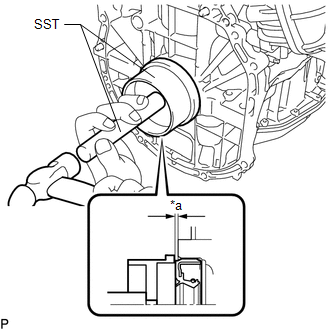
(a) Apply MP grease to the lip of a new rear engine oil seal.
NOTICE:
- Do not allow foreign matter to contact the lip of the rear engine oil seal.
- Do not allow MP grease to contact the dust seal.
| (b) Using SST and a hammer, tap in the rear engine oil seal until its surface is flush with the edges of the cylinder block and crankcase. SST: 09223-15030 SST: 09950-70010 09951-07150 Standard: 0 to 0.9 mm (0 to 0.0354 in.) (from edge of cylinder block) NOTICE:
|
|
2. INSTALL FLYWHEEL SUB-ASSEMBLY
| (a) Using SST, hold the crankshaft pulley assembly. SST: 09213-54015 SST: 09330-00021 HINT: Part number of installation bolt for SST (crankshaft pulley holding tool): 91551-80650 (quantity: 2) |
|
.png)
(b) Clean the bolts and bolt holes.
(c) Apply adhesive to 2 or 3 threads at the end of each of the 8 bolts.
Adhesive:
Toyota Genuine Adhesive 1324, Three Bond 1324 or equivalent
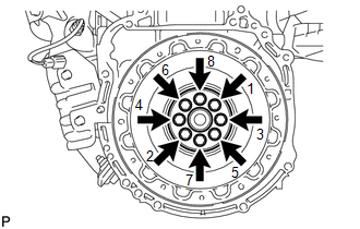
| (d) Install the flywheel sub-assembly with the 8 bolts. Uniformly tighten the 8 bolts in the sequence shown in the illustration. Torque: 130 N·m {1326 kgf·cm, 96 ft·lbf} |
|
3. INSTALL TRANSMISSION INPUT DAMPER ASSEMBLY
| (a) Using SST, hold the crankshaft pulley assembly. SST: 09213-54015 SST: 09330-00021 HINT: Part number of installation bolt for SST (crankshaft pulley holding tool): 91551-80650 (quantity: 2) |
|
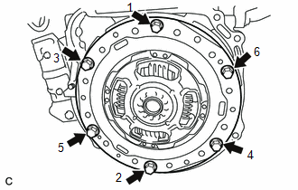
| (b) Install the transmission input damper assembly with the 6 bolts. Uniformly tighten the 6 bolts in the sequence shown in the illustration. Torque: 30 N·m {306 kgf·cm, 22 ft·lbf} NOTICE:
|
|
4. INSTALL HYBRID VEHICLE TRANSAXLE ASSEMBLY
Click here .gif)
READ NEXT:
 Components
COMPONENTS ILLUSTRATION *1 FUEL DELIVERY PIPE *2 FUEL INJECTOR ASSEMBLY *3 FUEL TUBE SUB-ASSEMBLY *4 INJECTOR VIBRATION INSULATOR *5 FUEL DELIVERY PIPE SPACER *6 O-RING
SEE MORE:
Components
COMPONENTS ILLUSTRATION *A for 8 Inch Display *B for 10.3 Inch Display *1 CENTER INSTRUMENT CLUSTER FINISH PANEL ASSEMBLY *2 CONSOLE ARMREST ASSEMBLY *3 INSTRUMENT CLUSTER FINISH PANEL SUB-ASSEMBLY *4 INSTRUMENT PANEL FINISH PLATE *5 INSTRUMENT SIDE PANEL LH *6
Diagnostic Trouble Code Chart
DIAGNOSTIC TROUBLE CODE CHART Parking Assist Monitor System DTC No. Detection Item Link C1611 ECU Malfunction C1621 Back Camera Power Supply Failure C1625 Open or Short in Steering Angle Sensor +B C1626 Steering Angle Sensor Failure C168D Vehi
