Lexus NX: Installation
INSTALLATION
PROCEDURE
1. INSTALL HV WATER PUMP BRACKET SUB-ASSEMBLY
| (a) Temporarily install the HV water pump bracket sub-assembly to the inverter bracket with bolt A. |
|
(b) Install bolt B.
Torque:
10 N·m {102 kgf·cm, 7 ft·lbf}
(c) Tighten bolt A.
Torque:
10 N·m {102 kgf·cm, 7 ft·lbf}
2. INSTALL WATER PUMP WITH MOTOR
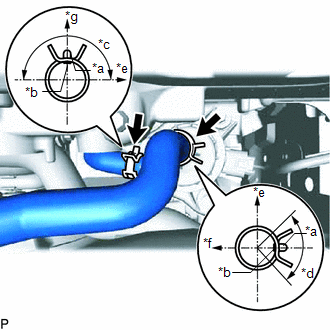
| (a) Connect the No. 2 inverter cooling hose and No. 3 inverter cooling hose to the water pump with motor, and slide the clamp to secure it. NOTICE:
|
|
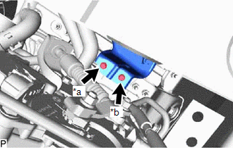
(b) Install the water pump with motor with the 3 bolts.
Torque:
6.1 N·m {62 kgf·cm, 54 in·lbf}
HINT:
First, temporarily install the 2 bolts, install the 3rd bolt with the specified torque, and then tighten the 2 bolts.
(c) Connect the water pump with motor connector.
3. CONNECT NO. 2 INVERTER COOLING HOSE ASSEMBLY
Click here .gif)
4. INSTALL UPPER RADIATOR SUPPORT SUB-ASSEMBLY
Click here
5. ADD COOLANT (for Inverter Coolant)
Click here
6. INSPECT FOR COOLANT LEAK (for Inverter Coolant)
Click here
7. INSTALL NO. 1 ENGINE UNDER COVER ASSEMBLY
Click here
READ NEXT:
 Components
COMPONENTS ILLUSTRATION *1 INVERTER RESERVOIR ASSEMBLY *2 NO. 1 ENGINE COVER SUB-ASSEMBLY *3 WIRE HARNESS - - N*m (kgf*cm, ft.*lbf): Specified torque - - ILLUSTRATION
SEE MORE:
Precaution
PRECAUTION PRECAUTION FOR DISCONNECTING CABLE FROM NEGATIVE AUXILIARY BATTERY TERMINAL NOTICE:
After turning the power switch off, waiting time may be required before disconnecting the cable from the negative (-) auxiliary battery terminal.
Click here
When disconnecting and reconnecting the a
Power Back Door cannot be Opened or Closed Using the Back Door Control Switch
DESCRIPTION When the power back door cannot be closed using the back door control switch, either of the following may be malfunctioning: 1) back door control switch circuit or 2) multiplex network door ECU. WIRING DIAGRAM CAUTION / NOTICE / HINT NOTICE: If the replacement, removal and installation
