Lexus NX: Installation
INSTALLATION
CAUTION / NOTICE / HINT
NOTICE:
- Do not replace the spiral with sensor cable sub-assembly with the battery connected and the engine switch on (IG).
- Do not rotate the spiral with sensor cable sub-assembly when the following conditions are met: 1) The steering wheel is removed, 2) the battery is connected,and 3) the engine switch is on (IG).
- Ensure that the steering wheel is installed and aligned straight when inspecting the steering sensor.
PROCEDURE
1. INSTALL NO. 2 STEERING INTERMEDIATE SHAFT ASSEMBLY
| (a) Align the matchmarks on the No. 2 steering intermediate shaft assembly and electric power steering column sub-assembly. |
|
.png)
(b) Install the bolt.
Torque:
35.3 N·m {360 kgf·cm, 26 ft·lbf}
2. INSTALL ELECTRIC POWER STEERING COLUMN SUB-ASSEMBLY
| (a) Install the electric power steering column sub-assembly with the bolt and 2 nuts. Torque: for Bolt : 36 N·m {367 kgf·cm, 27 ft·lbf} for Nut : 21 N·m {214 kgf·cm, 15 ft·lbf} NOTICE:
|
|
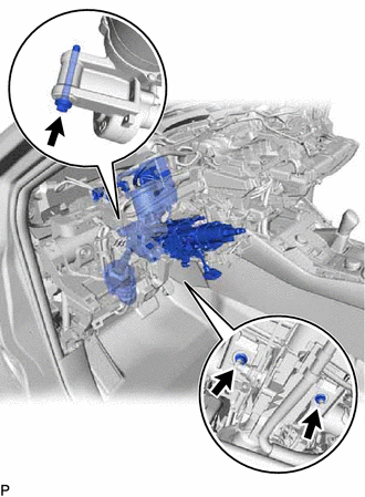
| (b) Connect the 2 connectors and attach the 3 clamps. |
|
.png)
(c) Connect the wire harness with the bolt.
Torque:
8.35 N·m {85 kgf·cm, 74 in·lbf}
3. INSTALL NO. 1 AIR DUCT
(a) Attach the 3 claws to install a new No. 1 air duct.
NOTICE:
If the No. 1 air duct is reused, it may fall off or abnormal noise may occur. Therefore, make sure to replace with a new one.
4. PLACE FRONT WHEELS FACING STRAIGHT AHEAD
5. CONNECT NO. 2 STEERING INTERMEDIATE SHAFT ASSEMBLY
| (a) Align the matchmarks on the No. 2 steering intermediate shaft assembly and steering intermediate shaft assembly. |
|
.png)
(b) Install the bolt.
Torque:
35.3 N·m {360 kgf·cm, 26 ft·lbf}
6. INSTALL COLUMN HOLE COVER SILENCER SHEET
(a) Install the column hole cover silencer sheet with the 2 clips.
(b) Install the floor carpet.
7. INSTALL LOWER NO. 1 INSTRUMENT PANEL AIRBAG ASSEMBLY
Click here .gif)
8. INSTALL UPPER INSTRUMENT PANEL SUB-ASSEMBLY
Click here
9. INSTALL COMBINATION SWITCH ASSEMBLY WITH SPIRAL CABLE SUB-ASSEMBLY
(a) Attach the 3 claws to install the combination switch assembly with spiral cable sub-assembly to the electric power steering column sub-assembly.
(b) Connect the connectors to the combination switch assembly with spiral cable sub-assembly.
10. INSTALL UPPER STEERING COLUMN COVER
(a) Attach the 4 clips, 3 claws and 2 pins to install the upper steering column cover.
11. INSTALL LOWER STEERING COLUMN COVER
(a) Attach the under side craw.
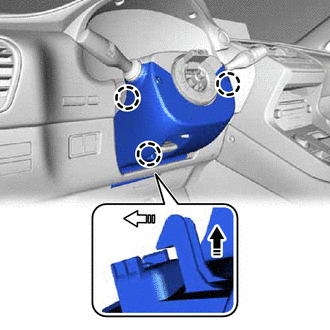
.png) | Install in this Direction (1) |
.png) | Install in this Direction (2) |
(b) Attach the 2 upper side claws to install the lower steering column cover.
NOTICE:
- Attach the claws one by one.
- Do not damage the tilt and telescopic switch.
(c) Install the 2 screws.
12. FRONT WHEELS FACING STRAIGHT AHEAD
13. ADJUST SPIRAL CABLE
Click here
14. INSTALL STEERING WHEEL ASSEMBLY
Click here
15. INSPECT STEERING WHEEL CENTER POINT
16. PERFORM ASSIST MAP WRITING
Click here
READ NEXT:
 Components
COMPONENTS ILLUSTRATION *1 COLUMN HOLE COVER SILENCER SHEET *2 COMBINATION SWITCH ASSEMBLY WITH SPIRAL CABLE SUB-ASSEMBLY *3 ELECTRIC POWER STEERING COLUMN SUB-ASSEMBLY *4 NO. 1 AI
Removal
REMOVAL CAUTION / NOTICE / HINT NOTICE:
Do not replace the spiral with sensor cable sub-assembly with the battery connected and the power switch on (IG).
Do not rotate the spiral with sensor cabl
SEE MORE:
Installation
INSTALLATION PROCEDURE 1. INSTALL COMBINATION SWITCH ASSEMBLY (for Upper Side) (a) Attach the 4 claws to install the combination switch assembly. 2. INSTALL NO. 2 COMBINATION SWITCH ASSEMBLY (for Lower Side) (a) Attach the 4 claws to install the No. 2 combination switch assembly.
DC / DC Converter Status Circuit Low Input (P0A09-265)
DESCRIPTION Refer to the description for DTC P0A08-264. Click here The hybrid vehicle control ECU sends a signal to the DC/DC converter to prohibit its control and receives signals indicating a normal or abnormal (below 11 V auxiliary battery voltage) condition of the 12 V charging system from th
