Lexus NX: Installation
INSTALLATION
PROCEDURE
1. INSTALL STEERING GEAR ASSEMBLY
(a) Install the steering gear assembly to the front suspension crossmember with the 2 bolts and 2 nuts.
Torque:
110 N·m {1122 kgf·cm, 81 ft·lbf}
NOTICE:
- Make sure to tighten the bolts starting from the left side of the vehicle.
- Because the nut has its own stopper, do not turn the nut. Tighten the bolt with the nut fixed in place.
2. INSTALL STEERING INTERMEDIATE SHAFT
| (a) Align the matchmarks and install the steering intermediate shaft to the steering gear assembly. |
|
.png)
(b) Install the bolt.
Torque:
35.3 N·m {360 kgf·cm, 26 ft·lbf}
3. INSTALL NO. 1 STEERING COLUMN HOLE COVER SUB-ASSEMBLY
| (a) Temporarily install the clamp to the No. 1 steering column hole cover sub-assembly. |
|
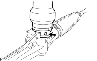
(b) Align the round hole in the No. 1 steering column hole cover sub-assembly with the protrusion of the steering gear assembly and install the cover.
(c) Install a new clamp.
4. INSTALL FRONT SUSPENSION CROSSMEMBER SUB-ASSEMBLY
Click here .gif)
5. INSTALL FRONT SUSPENSION MEMBER REAR BRACE LH
Click here
6. INSTALL FRONT SUSPENSION MEMBER REAR BRACE RH
HINT:
Use the same procedure described for the LH side.
7. INSTALL FRONT SUSPENSION MEMBER REINFORCEMENT LH
Click here
8. INSTALL FRONT SUSPENSION MEMBER REINFORCEMENT RH
HINT:
Use the same procedure described for the LH side.
9. CONNECT FRONT STABILIZER LINK ASSEMBLY LH
Click here
10. CONNECT FRONT STABILIZER LINK ASSEMBLY RH
HINT:
Use the same procedure described for the LH side.
11. CONNECT TIE ROD END SUB-ASSEMBLY LH
| (a) Connect the tie rod end sub-assembly to the steering knuckle with the nut. Torque: 49 N·m {500 kgf·cm, 36 ft·lbf} NOTICE: Tighten the nut up to an additional 60° if the holes for the cotter pin are not aligned. |
|
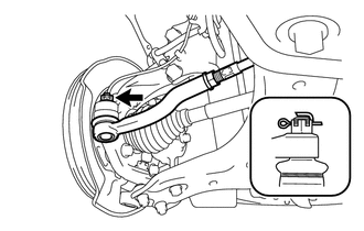
(b) Install a new cotter pin.
NOTICE:
Bend the cotter pin along the nut.
12. CONNECT TIE ROD END SUB-ASSEMBLY RH
HINT:
Use the same procedure described for the LH side.
13. CONNECT NO. 1 STEERING COLUMN HOLE COVER SUB-ASSEMBLY
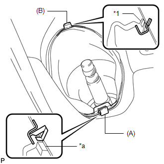
| (a) Install the clip (A) as shown in the illustration and engage the clip (B) to the body to connect the No. 1 steering column hole cover sub-assembly. NOTICE: Make sure that the lip of the No. 1 steering column hole cover sub-assembly is not damaged. |
|
14. CONNECT NO. 2 STEERING INTERMEDIATE SHAFT ASSEMBLY
.png)
| *a | Matchmark |
(a) Align the matchmarks and install the No. 2 steering intermediate shaft assembly to the intermediate shaft.
(b) Install the bolt.
Torque:
35.3 N·m {360 kgf·cm, 26 ft·lbf}
15. INSTALL COLUMN HOLE COVER SILENCER SHEET
(a) Install the column hole cover silencer sheet with the 2 clips.
(b) Install the floor carpet.
16. INSTALL FRONT WHEELS
Click here
17. POSITION FRONT WHEELS FACING STRAIGHT AHEAD
18. ADJUST FRONT WHEEL ALIGNMENT
Click here
19. INSTALL REAR ENGINE UNDER COVER LH
Click here
20. INSTALL REAR ENGINE UNDER COVER RH
Click here
21. INSTALL FRONT FLOOR COVER CENTER LH
Click here
22. INSTALL NO. 1 ENGINE UNDER COVER
Click here
READ NEXT:
SEE MORE:
 Engine compartment
Components
Fuse box
Engine coolant reservoir
Engine oil filler cap
Power control unit coolant reservoir
Brake fluid reservoir
Radiator
Condenser
Electric cooling fans
Engine oil level dipstick
Washer fluid tank
Engine compartment cover
■ Removing the engine compartmen
How To Proceed With Troubleshooting
CAUTION / NOTICE / HINT HINT:
Use the following procedure to troubleshoot the lighting system.
*: Use the Techstream.
PROCEDURE 1. VEHICLE BROUGHT TO WORKSHOP
NEXT 2. INSPECT AUXILIARY BATTERY VOLTAGE (a) Measure the auxiliary battery voltage with power swi
