Lexus NX: Installation
INSTALLATION
PROCEDURE
1. INSTALL FRONT STABILIZER BAR BUSHING LH
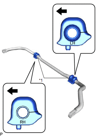
| *1 | Stopper |
.png) | Front of the Vehicle |
(a) Install the front stabilizer bar bushing to the front stabilizer bar as shown in the illustration.
NOTICE:
- Install the front stabilizer bar bushing so that the cutouts face the rear of the vehicle.
- Install the front stabilizer bar bushing LH so that the stopper of the front stabilizer bar is inside of the vehicle.
- Make sure that the LH and RH bushing are installed in the proper locations.
2. INSTALL FRONT STABILIZER BAR BUSHING RH
HINT:
Use the same procedure described for the LH side.
3. INSTALL FRONT STABILIZER BAR
(a) Install the front stabilizer bar to the front suspension crossmember so that the identification mark is positioned on the right side of the vehicle.
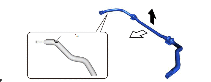
| *a | Identification Mark | - | - |
| | Top of the Vehicle |  | Front of the Vehicle |
4. TEMPORARILY INSTALL FRONT LOWER NO. 1 SUSPENSION ARM SUB-ASSEMBLY LH
Click here .gif)
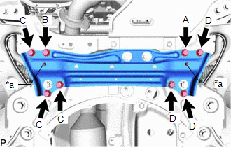
5. INSTALL FRONT SUSPENSION MEMBER BRACE
| (a) Install the front suspension member brace with the 8 bolts. Torque: 92 N·m {938 kgf·cm, 68 ft·lbf} NOTICE: After installing the front suspension member brace, make sure that the protrusions of the front stabilizer bar bushings are visible. |
|
6. INSTALL FRONT STABILIZER LINK ASSEMBLY LH
(a) Install the front stabilizer link assembly LH with the nut.
Torque:
74 N·m {755 kgf·cm, 55 ft·lbf}
HINT:
If the ball joint turns together with the nut, use a 6 mm hexagon wrench to hold the stud bolt.
7. INSTALL FRONT STABILIZER LINK ASSEMBLY RH
HINT:
Use the same procedure described for the LH side.
8. INSTALL FRONT SUSPENSION CROSSMEMBER SUB-ASSEMBLY
Click here
READ NEXT:
 Components
COMPONENTS ILLUSTRATION *1 FRONT CENTER FLOOR COVER LH *2 NO. 1 ENGINE UNDER COVER ASSEMBLY *3 REAR ENGINE UNDER COVER LH *4 REAR ENGINE UNDER COVER RH ILLUSTRATION *1 FRO
Removal
REMOVAL PROCEDURE 1. FRONT WHEELS FACING STRAIGHT AHEAD 2. SECURE STEERING WHEEL Click here 3. REMOVE COLUMN HOLE COVER SILENCER SHEET Click here 4. DISCONNECT NO. 2 STEERING INTERMEDIATE SHAFT AS
SEE MORE:
Components
COMPONENTS ILLUSTRATION *A for RH Side - - *1 REAR NO. 1 SEAT HEADREST SUPPORT ASSEMBLY *2 REAR SEAT CUSHION MOULDING RH *3 REAR SEAT CUSHION MOULDING RH *4 REAR SEAT HEADREST ASSEMBLY *5 REAR SEAT INNER WITH CENTER BELT ASSEMBLY RH *6 REAR SEATBACK BOARD CARP
Windshield wipers and washer
Operating the lever can switch
between automatic operation and
manual operation, or can use the
washer.
NOTICE
â– When the windshield is dry
Do not use the wipers, as they may damage
the windshield.
Operating the wiper lever
Operating the lever operates
the wipers or washer as follows.
â–
