Lexus NX: Installation
INSTALLATION
PROCEDURE
1. INSTALL REAR STABILIZER BUSHING
(a) Install the 2 rear stabilizer bushings to the rear stabilizer bar on the outside of the bush stoppers as shown in the illustration.
NOTICE:
- Install the rear stabilizer bushing so that the bushing stopper of the rear stabilizer bar is facing the vehicle interior.
- Install the rear stabilizer bushing so that the slit is in the position shown in the illustration.

| *1 | Rear Stabilizer Bushing |
| *a | Bushing Stopper |
| *b | Rear Stabilizer Bushing Slit |
.png) | Front of the Vehicle |
2. INSTALL REAR STABILIZER BAR
(a) Install the rear stabilizer bar so that the paint mark is facing the right side of the vehicle.
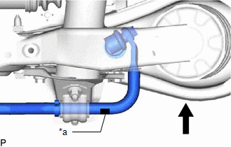
| *a | Paint Mark |
| | Front of the Vehicle |
3. INSTALL REAR NO. 1 STABILIZER BAR BRACKET
| (a) Install the 2 rear No. 1 stabilizer bar brackets to the rear suspension member with the 4 nuts. Torque: 60 N·m {612 kgf·cm, 44 ft·lbf} |
|
.png)
4. INSTALL REAR STABILIZER LINK ASSEMBLY LH
NOTICE:
Since the rear stabilizer link, rear stabilizer cushions and nut (B) are not reusable, new parts must be installed.
(a) Install a new rear stabilizer link assembly LH and 2 new rear stabilizer cushions to the rear No. 2 suspension arm assembly with a new nut (B) as shown in the illustration.
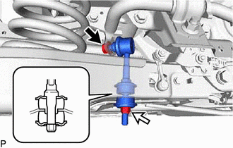
| | Nut (A) |
.png) | Nut (B) |
Torque:
30 N·m {306 kgf·cm, 22 ft·lbf}
NOTICE:
Be sure to install the rear stabilizer cushions in the correct direction as shown in the illustration.
(b) Install the rear stabilizer link assembly LH to the rear stabilizer bar with the nut (A).
Torque:
74 N·m {755 kgf·cm, 55 ft·lbf}
HINT:
If the ball joint turns together with the nut, use a 6 mm hexagon wrench to hold the stud.
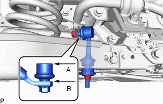
| (c) Adjust the rear stabilizer link assembly LH so that A and B are parallel as shown in the illustration. |
|
5. INSTALL REAR STABILIZER LINK ASSEMBLY RH
HINT:
Use the same procedure described for the LH side.
6. INSPECT AND ADJUST REAR WHEEL ALIGNMENT
Click here .gif)
READ NEXT:
 Components
COMPONENTS ILLUSTRATION *1 DECK FLOOR BOX LH *2 NO. 3 DECK BOARD SUB-ASSEMBLY *3 REAR DECK FLOOR BOX *4 NEGATIVE AUXILIARY BATTERY TERMINAL N*m (kgf*cm, ft.*lbf): Specified
Removal
REMOVAL CAUTION / NOTICE / HINT NOTICE:
When the brake pedal is first depressed after replacing the brake pads or pushing back the disc brake piston, DTC C1214 may be output. As there is no malfunc
SEE MORE:
System Description
SYSTEM DESCRIPTION POWER DOOR LOCK CONTROL SYSTEM DESCRIPTION (a) The power door lock system locks/unlocks all doors. The main body ECU (multiplex network body ECU) receives lock/unlock request signals from a door control switch or the driver door key lock and unlock switch. Then, the main body ECU
Open in Inside Luggage Compartment Electrical Key Oscillator Circuit (B27A7)
DESCRIPTION The certification ECU (smart key ECU assembly) generates a request signal and transmits the signal to the No. 3 indoor electrical key antenna assembly (inside luggage). For the No. 3 indoor electrical key antenna assembly (inside luggage) to detect when the electrical key transmitter sub
