Lexus NX: Installation
INSTALLATION
PROCEDURE
1. INSTALL KICK DOOR CONTROL SENSOR
| (a) Insert the guide, attach the 2 claws and install the kick door control sensor to the kick door control bracket as shown in the illustration. NOTICE:
|
|
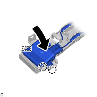
| (b) Connect the wire (red) to the kick door control bracket and attach the clamp. NOTICE:
|
|
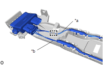
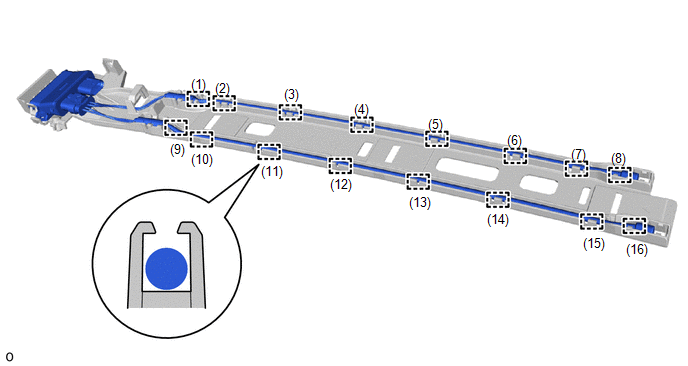
(c) Attach the 16 claws in the order shown in the illustration and connect the antenna.
NOTICE:
Securely insert the antenna into the bracket until it reaches the bottom.
2. INSTALL KICK DOOR CONTROL BRACKET
(a) Attach the 3 guides and temporarily install the kick door control bracket together with the kick door control sensor as shown in the illustration.
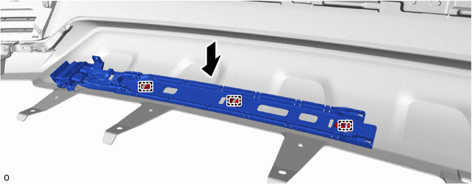
(b) Align the kick door control bracket with the arrow and install the kick door control bracket with the 3 outside moulding retainers as shown in the illustration.
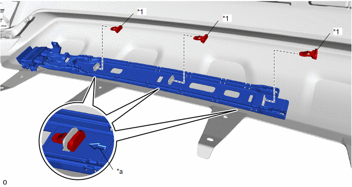
| *1 | Outside Moulding Retainer | - | - |
| *a | Install in this Direction | - | - |
(c) Install the screw.
(d) Attach the 2 wire harness clamps and connect the connector.
NOTICE:
Do not touch the terminal of the kick door control sensor connector.
3. INSTALL REAR BUMPER COVER
Click here .gif)
4. OPERATION CHECK KICK DOOR CONTROL SENSOR
Click here
READ NEXT:
 Power Back Door Control Switch
ComponentsCOMPONENTS ILLUSTRATION *1 BACK DOOR CONTROL SWITCH *2 PULL HANDLE RemovalREMOVAL PROCEDURE 1. REMOVE PULL HANDLE Click here 2. REMOVE BACK DOOR CONTROL SWITCH (a) Detach
Components
COMPONENTS ILLUSTRATION *A w/ Woofer *B w/o Woofer *1 BACK DOOR CENTER GARNISH *2 BACK DOOR LOCK COVER *3 BACK DOOR SIDE GARNISH LH *4 BACK DOOR SIDE GARNISH RH *5
SEE MORE:
Parts Location
PARTS LOCATION ILLUSTRATION *1 NO. 2 ENGINE ROOM RELAY BLOCK - ODS FUSE *2 FRONT SEAT INNER BELT ASSEMBLY RH *3 AIR CONDITIONING CONTROL ASSEMBLY *4 OCCUPANT DETECTION ECU *5 COMBINATION METER ASSEMBLY *6 AIRBAG ECU ASSEMBLY *7 FRONT OCCUPANT CLASSIFICATION SENSOR
Calibration
CALIBRATION DESCRIPTION (a) After replacing any VSC related components or performing wheel alignment adjustment, clear and read the sensor calibration data. Refer to the table below and then perform the necessary operation according to the part to be replaced in order to perform calibration. Part
