Lexus NX: Installation
INSTALLATION
CAUTION / NOTICE / HINT
HINT:
- Use the same procedure for the RH and LH sides.
- The procedure listed below is for the LH side.
PROCEDURE
1. REPAIR INSTRUCTION
Click here .gif)
2. INSTALL NO. 3 BLACK OUT TAPE LH
HINT:
When installing the No. 3 black out tape LH, heat the front door panel and No. 3 black out tape LH using a heat light.
Standard:
| Item | Temperature |
|---|---|
| Front Door Panel | 40 to 60°C (104 to 140°F) |
| No. 3 Black Out Tape LH | 20 to 30°C (68 to 86°F) |
NOTICE:
Do not heat the front door panel or No. 3 black out tape LH excessively.
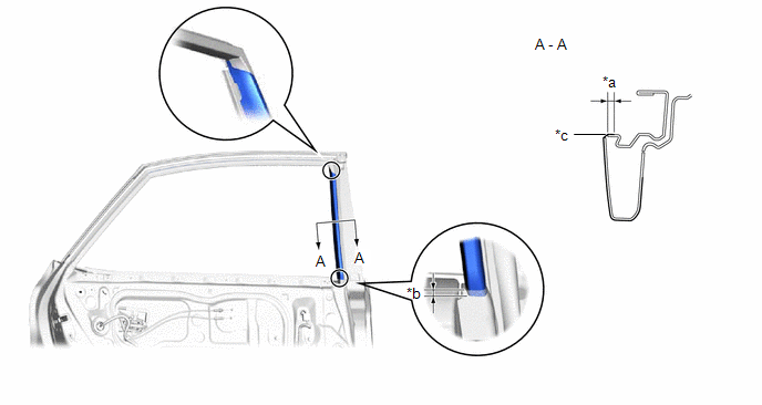
(a) Refer to the illustration to position a new No. 3 black out tape LH.
| *a | 1.5 mm (0.0591 in.) | *b | 1.0 mm (0.0394 in.) |
| *c | 5.0 mm (0.197 in.) | *d | Edge of Curved Surface |
(b) Remove the release paper from the No. 3 black out tape LH.
3. INSTALL NO. 2 BLACK OUT TAPE LH
HINT:
When installing the No. 2 black out tape LH, heat the front door panel and No. 2 black out tape LH using a heat light.
Standard:
| Item | Temperature |
|---|---|
| Front Door Panel | 40 to 60°C (104 to 140°F) |
| No. 2 Black Out Tape LH | 20 to 30°C (68 to 86°F) |
NOTICE:
Do not heat the front door panel or No. 2 black out tape LH excessively.
(a) Refer to the illustration to position a new No. 2 black out tape LH.
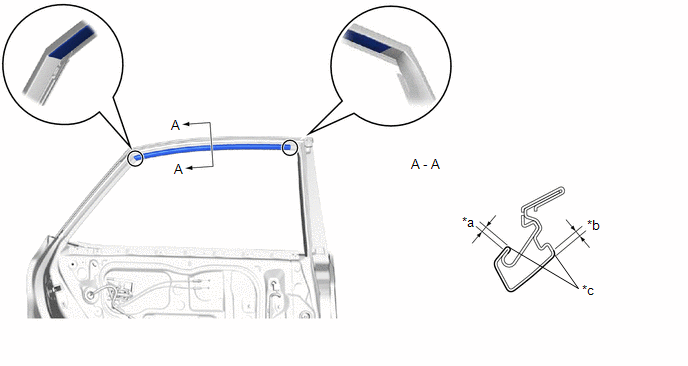
| *a | 1.5 mm (0.0591 in.) | *b | 1.0 mm (0.0394 in.) |
| *c | Edge of Curved Surface | - | - |
(b) Remove the release paper from the No. 2 black out tape LH.
4. INSTALL NO. 1 BLACK OUT TAPE LH
HINT:
When installing the No. 1 black out tape LH, heat the front door panel and No. 1 black out tape LH using a heat light.
Standard:
| Item | Temperature |
|---|---|
| Front Door Panel | 40 to 60°C (104 to 140°F) |
| No. 1 Black Out Tape LH | 20 to 30°C (68 to 86°F) |
NOTICE:
Do not heat the front door panel or No. 1 black out tape LH excessively.
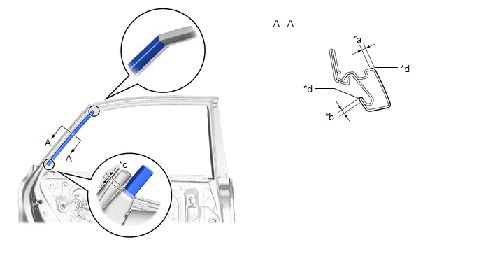
(a) Refer to the illustration to position a new No. 1 black out tape LH.
| *a | 1.0 mm (0.0394 in.) | *b | 5.0 mm (0.197 in.) |
| *c | Edge of Curved Surface | - | - |
(b) Remove the release paper from the No. 1 black out tape LH.
5. INSTALL REAR DOOR REAR WINDOW FRAME MOULDING LH
Click here
6. INSTALL REAR DOOR UPPER WINDOW FRAME MOULDING LH
Click here
7. INSTALL REAR DOOR FRONT WINDOW FRAME MOULDING LH
Click here
8. INSTALL REAR DOOR BELT MOULDING ASSEMBLY LH
Click here
9. INSTALL REAR DOOR FRAME GARNISH LH
Click here
10. INSTALL REAR DOOR WEATHERSTRIP LH
Click here
11. CONNECT REAR DOOR CHECK ASSEMBLY LH
(a) Apply MP grease to the sliding area of the rear door check assembly LH.
(b) When reusing a bolt:
(1) Clean the threads of the bolt with non-residue solvent.
(2) Apply adhesive to the threads of the bolt.
Adhesive:
Toyota Genuine Adhesive 1324, Three Bond 1324 or equivalent.
| (c) Connect the rear door check assembly LH with the bolt. Torque: 27 N·m {275 kgf·cm, 20 ft·lbf} |
|
.png)
12. INSTALL REAR DOOR GLASS SUB-ASSEMBLY LH
Click here
13. INSTALL REAR DOOR REAR GUIDE SEAL LH
Click here
14. INSTALL REAR DOOR REAR LOWER WINDOW FRAME SUB-ASSEMBLY LH
Click here
15. INSTALL REAR DOOR GLASS RUN LH
Click here
16. INSTALL REAR DOOR SERVICE HOLE COVER LH
Click here
17. INSTALL REAR DOOR ARMREST SET BRACKET LH
Click here
18. INSTALL REAR DOOR INNER GLASS WEATHERSTRIP LH
Click here
19. INSTALL REAR DOOR TRIM BOARD SUB-ASSEMBLY LH
Click here
20. INSTALL REAR POWER WINDOW REGULATOR SWITCH ASSEMBLY WITH REAR DOOR ARMREST BASE PANEL
Click here
21. INSTALL REAR DOOR INSIDE HANDLE BEZEL PLUG LH
Click here
22. INSTALL REAR DOOR TRIM COVER LH
Click here
23. CONNECT CABLE TO NEGATIVE AUXILIARY BATTERY TERMINAL
NOTICE:
When disconnecting the cable, some systems need to be initialized after the cable is reconnected.
Click here
24. INITIALIZATION AFTER RECONNECTING AUXILIARY BATTERY TERMINAL
Click here
HINT:
When disconnecting and reconnecting the auxiliary battery, there is an automatic learning function that completes learning when the respective system is used.
Click here
25. INSTALL DECK FLOOR BOX LH
Click here
26. INSTALL REAR DECK FLOOR BOX
Click here
27. INSTALL NO. 3 DECK BOARD SUB-ASSEMBLY
Click here
28. INITIALIZE POWER WINDOW CONTROL SYSTEM
Click here
29. CHECK POWER WINDOW CONTROL SYSTEM
Click here
READ NEXT:
 Components
COMPONENTS ILLUSTRATION *1 FRONT BUMPER ASSEMBLY *2 FRONT FENDER FRONT SPLASH SHIELD LH *3 FRONT FENDER FRONT SPLASH SHIELD RH *4 RADIATOR GRILLE PROTECTOR *5 RADIATOR SUPPOR
Removal
REMOVAL CAUTION / NOTICE / HINT HINT: When the front bumper is damaged or deformed due to an accident or contact with other objects, etc., or the bumper installation area on the body is repaired, it i
SEE MORE:
Removal
REMOVAL PROCEDURE 1. REMOVE FRONT SEAT ASSEMBLY LH Click here 2. REMOVE FRONT SEAT ASSEMBLY RH HINT: Use the same procedure as for the driver seat. 3. REMOVE FRONT SEAT INNER BELT ASSEMBLY LH (a) Disconnect the 2 connectors. (b) Detach the 6 clamps. (c) Detach the clamp.
Reassembly
REASSEMBLY CAUTION / NOTICE / HINT HINT: Perform "Inspection After Repairs" after replacing the cylinder head sub-assembly. Click here PROCEDURE 1. INSTALL CYLINDER HEAD STUD BOLT NOTICE: If a stud bolt is deformed or its threads are damaged, replace it. (a) Using an E7 "TORX" socket wrench, in
