Lexus NX: Installation
INSTALLATION
CAUTION / NOTICE / HINT
HINT:
- Use the same procedure for the RH and LH sides.
- The procedures listed below are for the LH side.
PROCEDURE
1. INSTALL FRONT DOOR LOWER OUTSIDE MOULDING SUB-ASSEMBLY LH
HINT:
When installing the front door lower outside moulding sub-assembly LH, heat the front door panel and front door lower outside moulding sub-assembly LH using a heat light.
Standard:
| Item | Temperature |
|---|---|
| Front Door Panel | 40 to 60°C (104 to 140°F) |
| Front Door Lower Outside Moulding Sub-assembly LH | 20 to 30°C (68 to 86°F) |
NOTICE:
Do not heat the front door panel and front door lower outside moulding sub-assembly LH excessively.
(a) Clean the front door panel surface.
(1) Using a heat light, heat the front door panel surface.
(2) Remove the double-sided tape from the front door panel surface.
(3) Wipe off any tape adhesive residue with cleaner.
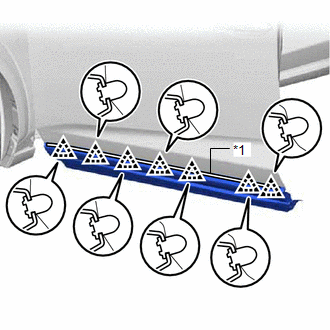
| (b) Install the front door lower outside moulding sub-assembly LH. (1) Using a heat light, heat the front door lower outside moulding sub-assembly LH and the front door panel surface. (2) Remove the peeling paper from the face of the front door outside moulding upper pad. HINT: After removing the peeling paper, keep the exposed adhesive free from foreign matter. (3) Attach the 7 clips and double-sided tape to install the front door lower outside moulding sub-assembly LH. HINT: Press the front door lower outside moulding sub-assembly LH firmly to install it. |
|
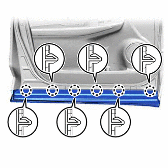
| (c) Attach the 6 claws. |
|
READ NEXT:
 Components
COMPONENTS ILLUSTRATION *1 DECK FLOOR BOX LH *2 NO. 3 DECK BOARD SUB-ASSEMBLY *3 REAR DECK FLOOR BOX *4 NEGATIVE AUXILIARY BATTERY TERMINAL N*m (kgf*cm, ft.*lbf): Specified
Removal
REMOVAL CAUTION / NOTICE / HINT HINT:
Use the same procedure for the RH and LH sides.
The procedure listed below is for the LH side.
PROCEDURE 1. PRECAUTION NOTICE: After the power switch off
SEE MORE:
Antenna Coil Open / Short (B2784)
DESCRIPTION When an open or short circuit is detected in the transponder key amplifier coil built into the power switch, the certification ECU (smart key ECU assembly) stores this DTC. This DTC is also stored as a past DTC. DTC No. Detection Item DTC Detection Condition Trouble Area Note
Installation
INSTALLATION PROCEDURE 1. INSTALL OCCUPANT DETECTION ECU (a) Attach the claw to install the occupant detection ECU. NOTICE: If the occupant detection ECU has been dropped, or there are any cracks, dents or other defects in the case or connector, replace the occupant detection ECU with a new one. (b)
