Lexus NX: Installation
INSTALLATION
PROCEDURE
1. INSTALL REAR BUMPER SIDE SUPPORT LH
| (a) Attach the 2 claws to install the rear bumper side support LH. |
|
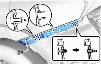
(b) Attach the clip.
(c) Install the screw.
2. INSTALL REAR BUMPER SIDE SUPPORT RH
HINT:
Use the same procedure as for the LH side.
3. INSTALL REAR BUMPER SIDE SEAL LH
| (a) Install the rear bumper side seal LH with 2 new grommets. |
|
.png)
4. INSTALL REAR BUMPER SIDE SEAL RH
HINT:
Use the same procedure as for the LH side.
5. INSTALL REAR BUMPER NO. 1 REINFORCEMENT
| (a) Install the rear bumper No. 1 reinforcement with the 8 bolts. Torque: 37 N·m {377 kgf·cm, 27 ft·lbf} |
|
.png)
6. INSTALL REAR BUMPER COVER
(a) Attach the 16 claws to install the rear bumper cover.
(b) w/ Intuitive Parking Assist System, Hands Free Power Back Door:
(1) Connect the connector.
(c) Install the 2 screws labeled B.
(d) Install the 4 screws labeled A.
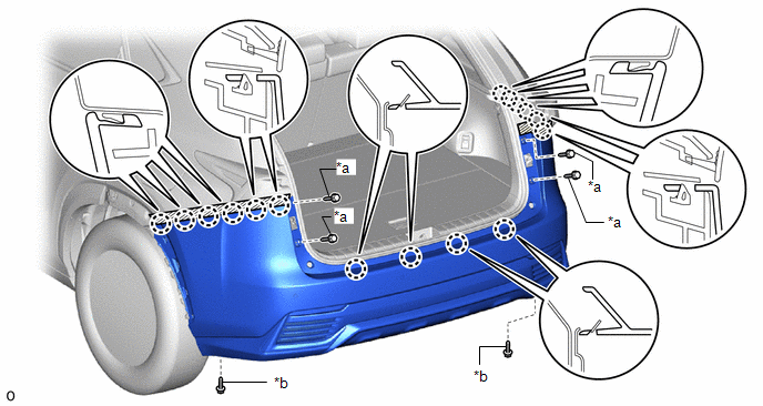
| *a | Screw A | *b | Screw B |
(e) Remove the protective tape.
| (f) Install the clip. HINT: Use the same procedure to install the clip on the other side. |
|
.png)
7. INSTALL REAR BUMPER NO. 1 PLATE
| (a) Attach the 2 claws to install the rear bumper No. 1 plate. HINT: Use the same procedure for all rear bumper No. 1 plates. |
|
.png)
8. INSTALL REAR FLOOR SIDE MEMBER COVER
| (a) Install the rear floor side member cover with the 8 clips. |
|
.png)
9. INSTALL REAR LOWER QUARTER MOULDING PROTECTOR LH
Click here .gif)
10. INSTALL REAR LOWER QUARTER MOULDING PROTECTOR RH
HINT:
Use the same procedure as for the LH side.
11. INSTALL NO. 5 MOULDING TAPE
Click here
12. INSTALL QUARTER OUTSIDE MOULDING SUB-ASSEMBLY LH
Click here
13. INSTALL QUARTER OUTSIDE MOULDING SUB-ASSEMBLY RH
HINT:
Use the same procedure as for the LH side.
14. INSPECT KICK DOOR CONTROL SENSOR (w/ Hands Free Power Back Door)
Click here
15. PERFORM CALIBRATION (w/ Intelligent Clearance Sonar System)
Click here
READ NEXT:
 Components
COMPONENTS ILLUSTRATION *1 DECK FLOOR BOX LH *2 NO. 3 DECK BOARD SUB-ASSEMBLY *3 REAR DECK FLOOR BOX *4 NEGATIVE AUXILIARY BATTERY TERMINAL N*m (kgf*cm, ft.*lbf): Specified
Removal
REMOVAL CAUTION / NOTICE / HINT HINT:
Use the same procedure for the RH and LH sides.
The procedure listed below is for the LH side.
PROCEDURE 1. PRECAUTION NOTICE: After the power switch off
SEE MORE:
Mute Signal Circuit between Stereo Component Amplifier and Telematics Transceiver
DESCRIPTION This DCM (telematics transceiver) sends a mute signal to the stereo component amplifier assembly. The stereo component amplifier assembly controls the volume according to the mute signal from the DCM (telematics transceiver). If there is an open in the circuit, noise can be heard from th
Installation
INSTALLATION PROCEDURE 1. INSTALL NO. 3 MOTOR WATER JACKET COVER ASSEMBLY Click here 2. INSTALL NO. 1 MOTOR WATER JACKET COVER ASSEMBLY Click here 3. INSTALL NO. 2 MOTOR WATER JACKET COVER ASSEMBLY Click here 4. INSTALL MOTOR CONNECTOR PROTECTOR (a) Apply adhesive to the 2 stud bolts. Adhesive
