Lexus NX: Installation
INSTALLATION
PROCEDURE
1. INSTALL BACK DOOR LOCK ASSEMBLY (w/ Power Back Door)
NOTICE:
- When installing a new back door lock assembly, if there is any tape stuck to it, remove the tape.
- When installing a new back door lock assembly, if there are any strings attached to it, cut the strings off.
- Do not allow grease or dust to adhere to the door lock wiring harness seal surface of the connector.
(a) Apply MP grease to the sliding parts of the back door lock assembly.
| (b) Temporarily install the 4 bolts in the order shown in the illustration. |
|
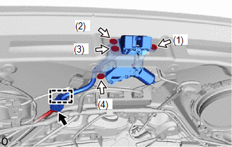
(c) Tighten the 4 bolts.
Torque:
13 N·m {133 kgf·cm, 10 ft·lbf}
(d) Attach the clamp.
(e) Connect the connector.
2. INSTALL BACK DOOR LOCK ASSEMBLY (w/o Power Back Door)
NOTICE:
- When installing a new back door lock assembly, if there is any tape stuck to it, remove the tape.
- When installing a new back door lock assembly, if there are any strings attached to it, cut the strings off.
- Do not allow grease or dust to adhere to the door lock wiring harness seal surface of the connector.
(a) Apply MP grease to the sliding parts of the back door lock assembly.
(b) Install the back door lock assembly with the 3 bolts.
Torque:
13 N·m {133 kgf·cm, 10 ft·lbf}
(c) Connect the connector.
3. INSTALL BACK DOOR TRIM BOARD ASSEMBLY
Click here .gif)
4. INSTALL BACK DOOR LOCK COVER (w/ Power Back Door)
Click here
5. INSTALL BACK DOOR LOCK COVER (w/o Power Back Door)
Click here
6. INSTALL BACK DOOR TRIM BASE (w/ Power Back Door)
Click here
7. INSTALL PULL HANDLE (w/ Power Back Door)
Click here
8. INSTALL BACK DOOR FINISH COVER LH (w/o Power Back Door)
Click here
9. INSTALL BACK DOOR FINISH COVER RH (w/o Power Back Door)
HINT:
Use the same procedure as for the LH side.
10. INSTALL BACK DOOR SIDE GARNISH LH
Click here
11. INSTALL BACK DOOR SIDE GARNISH RH
HINT:
Use the same procedure as for the LH side.
12. INSTALL BACK DOOR CENTER GARNISH
(a) Attach the 2 guides and 5 claws to install the back door center garnish.
13. INSPECT POWER BACK DOOR SYSTEM (w/ Power Back Door)
Click here
14. INSPECT BACK DOOR CLOSER SYSTEM (w/ Power Back Door)
Click here
READ NEXT:
 Components
COMPONENTS ILLUSTRATION *1 DECK FLOOR BOX LH *2 NO. 3 DECK BOARD SUB-ASSEMBLY *3 REAR DECK FLOOR BOX *4 NEGATIVE AUXILIARY BATTERY TERMINAL N*m (kgf*cm, ft.*lbf): Specified
Removal
REMOVAL PROCEDURE 1. PRECAUTION NOTICE: After turning the power switch off, waiting time may be required before disconnecting the cable from the negative (-) auxiliary battery terminal. Click here 2
SEE MORE:
Power Back Door cannot be Operated Using Kick Sensor
DESCRIPTION The kick door control sensor receives vehicle speed, IG and ACC signals from the main body ECU (multiplex network body ECU) via LIN communication and uses the information to stop sensor oscillation. When the kick door control sensor detects a kick operation, it sends a operation signal t
Short in Motor Circuit (C1521-C1524,C1528,C1531-C1555)
DESCRIPTION The power steering ECU assembly detects steering force using the signal received from the steering torque sensor, and also monitors the motor circuit for errors. DTC No. Detection Item DTC Detection Condition Trouble Area Warning Indicate Return-to-normal Condition Note
