Lexus NX: Installation
INSTALLATION
PROCEDURE
1. INSTALL CLOCK ASSEMBLY
| (a) Attach the 2 claws to install the clock assembly. |
|
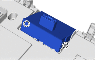
2. INSTALL AIR CONDITIONING CONTROL ASSEMBLY
| (a) Connect the connectors. |
|
.png)
(b) Attach the 6 clips to install the air conditioning control assembly.
3. INSTALL CENTER INSTRUMENT CLUSTER FINISH PANEL ASSEMBLY
Click here .gif)
4. INSTALL MULTI-DISPLAY ASSEMBLY WITH BRACKET
Click here
5. INSTALL INSTRUMENT PANEL FINISH PLATE
Click here
6. INSTALL NO. 2 INSTRUMENT PANEL SAFETY PAD SUB-ASSEMBLY
Click here
7. INSTALL INSTRUMENT SIDE PANEL RH
Click here
8. INSTALL NO. 1 SWITCH HOLE BASE
Click here
9. INSTALL LOWER NO. 1 INSTRUMENT PANEL FINISH PANEL
Click here
10. INSTALL NO. 1 INSTRUMENT PANEL UNDER COVER SUB-ASSEMBLY
Click here
11. INSTALL NO. 1 INSTRUMENT PANEL SAFETY PAD SUB-ASSEMBLY
Click here
12. INSTALL INSTRUMENT SIDE PANEL LH
Click here
13. INSTALL UPPER NO. 2 CONSOLE PANEL GARNISH
Click here
14. INSTALL UPPER NO. 1 CONSOLE PANEL GARNISH
Click here
15. INSTALL UPPER REAR CONSOLE PANEL
Click here
16. INSTALL CONSOLE ARMREST ASSEMBLY
Click here
READ NEXT:
 Parts Location
PARTS LOCATION ILLUSTRATION *1 CLOCK ASSEMBLY *2 COMBINATION METER ASSEMBLY *3 RADIO RECEIVER ASSEMBLY *4 INSTRUMENT PANEL JUNCTION BLOCK ASSEMBLY - ACC FUSE - PANEL FUSE *5
System Diagram
SYSTEM DIAGRAM
SEE MORE:
IG Power Source Circuit
DESCRIPTION When the power switch is turned on (IG), the IG power source circuit supplies positive (+) voltage to the multiplex tilt and telescopic ECU. The multiplex tilt and telescopic ECU also receives power switch signals via this circuit. WIRING DIAGRAM CAUTION / NOTICE / HINT NOTICE: Inspect
Thermostat
ComponentsCOMPONENTS ILLUSTRATION *1 THERMOSTAT *2 WATER INLET *3 GASKET - - N*m (kgf*cm, ft.*lbf): Specified torque ● Non-reusable part RemovalREMOVAL PROCEDURE 1. DRAIN ENGINE COOLANT Click here 2. DISCONNECT WATER INLET (a) Remove the 2 nuts and disconne
