Lexus NX: Installation
INSTALLATION
CAUTION / NOTICE / HINT
HINT:
- Use the same procedure for the RH and LH sides.
- The procedure listed below is for the LH side.
PROCEDURE
1. INSTALL CURTAIN SHIELD AIRBAG ASSEMBLY LH
(a) Check that the power switch is off.
(b) Check that the cable is disconnected from the negative (-) auxiliary battery terminal.
CAUTION:
Wait at least 90 seconds after disconnecting the cable from the negative (-) auxiliary battery terminal to disable the SRS system.
| (c) Attach the 2 claws and install a new curtain shield airbag spacer and a new clip to the curtain shield airbag assembly LH. NOTICE: At this time, do not push in the pin to lock the clip. HINT: Use the same procedure for the other clips. |
|
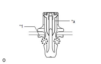
| (d) Attach the 2 claws and install a new curtain shield airbag spacer and a new clip to the curtain shield airbag assembly LH. NOTICE: At this time, do not push in the pin to lock the clip. HINT: Use the same procedure for the other clips. |
|
(e) Attach the 2 hooks and temporarily install the inflator with the 2 new bolts.
(f) Attach the 2 claws of the vehicle rear side deployment portion.
(g) Attach the 2 hooks to temporarily install the new bolts.
(h) Connect the vehicle rear side deployment portion for the curtain shield airbag assembly LH with the clip.
NOTICE:
At this time, do not push in the pin to lock the clip.
(i) Attach the 2 claws of the vehicle front side deployment portion.
(j) Connect the vehicle front side deployment portion for the curtain shield airbag assembly LH with the clip.
NOTICE:
At this time, do not push in the pin to lock the clip.
(k) Check that there is no twisting in the deployment portion of the curtain shield airbag assembly LH after connecting.
(l) Install the 3 bolts in the order shown in the illustration.
Torque:
9.8 N·m {100 kgf·cm, 87 in·lbf}
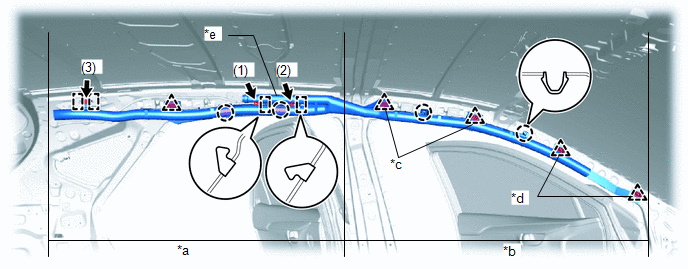
| *a | Vehicle Rear Side Deployment Portion | *b | Vehicle Front Side Deployment Portion |
| *c | Clip w/o Spacer | *d | Clip w/ Spacer |
| *e | Inflator | - | - |
(m) Using needle-nose pliers, push the pin to lock the clip.
NOTICE:
Make sure the pin is securely locked.
HINT:
Use the same procedure to lock the other clips.
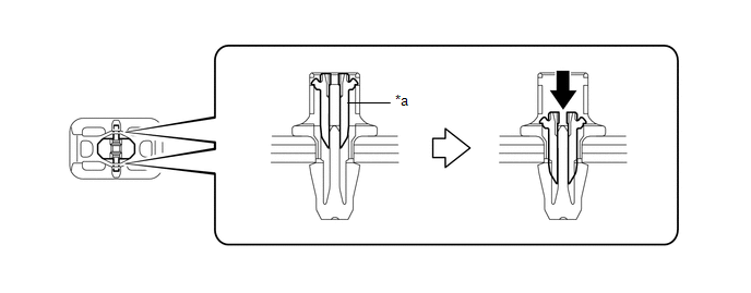
| *a | Pin | - | - |
(n) Lightly pull on the clip to check whether it is locked.
HINT:
Use the same procedure to check the other clips.
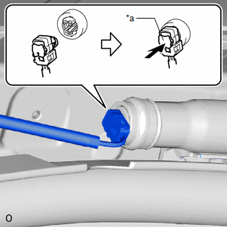
| (o) Connect the airbag connector and push the connector lock. NOTICE: When connecting any airbag connector, take care not to damage the airbag wire harness. |
|
2. INSTALL ROOF HEADLINING ASSEMBLY
Click here .gif)
3. CONNECT CABLE TO NEGATIVE AUXILIARY BATTERY TERMINAL
(a) Connect the cable to the negative (-) auxiliary battery terminal and tighten the nut.
Torque:
5.4 N·m {55 kgf·cm, 48 in·lbf}
4. INITIALIZATION AFTER RECONNECTING AUXILIARY BATTERY TERMINAL
Click here
HINT:
When disconnecting and reconnecting the auxiliary battery, there is an automatic learning function that completes learning when the respective system is used.
Click here
5. INSTALL DECK FLOOR BOX LH
Click here
6. INSTALL REAR DECK FLOOR BOX
Click here
7. INSTALL NO. 3 DECK BOARD SUB-ASSEMBLY
Click here
8. PERFORM DIAGNOSTIC SYSTEM CHECK
Click here
9. CHECK SRS WARNING LIGHT
Click here
READ NEXT:
 Components
COMPONENTS ILLUSTRATION *1 DECK FLOOR BOX LH *2 NO. 3 DECK BOARD SUB-ASSEMBLY *3 REAR DECK FLOOR BOX *4 AUXILIARY BATTERY NEGATIVE TERMINAL N*m (kgf*cm, ft.*lbf): Specified
On-vehicle Inspection
ON-VEHICLE INSPECTION CAUTION / NOTICE / HINT CAUTION: Be sure to follow the correct removal and installation procedures of the front airbag sensors. PROCEDURE 1. INSPECT FRONT AIRBAG SENSOR (for Vehi
SEE MORE:
Removal
REMOVAL PROCEDURE 1. PRECAUTION (a) w/ Parking Assist Monitor System: Click here (b) w/ Panoramic View Monitor System: Click here 2. REMOVE BACK DOOR TRIM BASE (w/ Power Back Door) Click here 3. REMOVE PULL HANDLE (w/ Power Back Door) Click here 4. REMOVE BACK DOOR FINISH COVER LH (w/o Power
Operation Check
OPERATION CHECK AUTOMATIC HIGH BEAM SYSTEM OPERATION CHECK (a) Check the operation of the automatic high beam indicator light. *a Automatic High Beam Indicator Light NOTICE: If the forward recognition camera cannot correctly recognize the front due to bad weather (dense fog, etc.) or obstru
